This blog post will cover the build process for Aurora up, if you want to find out about how it was built you can read about it here, If you’d like to look at the code you can see the github
It’s often easier to ask something that can be answered quickly than spend hours trying to figure something out, for that reason there is a Slack setup here to for any questions you may have: Click here to join
Overview
This project needs a few key components, I have my recommended minimums for each one and what I am running, but you can easily get better versions of everything, in almost every category these upgrades are not needed. If you do want to have slightly better items I suggest the HDMI splitter and the LED strip. For the HDMI splitter the upgraded version (as per ezcoolav team) may have a future firmware for it will have better colour sampling in the downscaling (so it matches more closely). The LED strip means that if you buy strips with more LEDs/m you will get higher “clarity” with the image on the screen. The TLDR is:
- Pi4 2gb or 4gb – $35 or $50 you can use this to figure out where to buy or just grab a canakit kit (lol)
- HDMI Capture Card – $8 – Try this one
- HDMI splitter – $29 OR $47 for the better one – $29 one or $47 one
- LED Strip – $25 for 5m/16.4ft LED strip with 300 LEDs – I used this one
- Power supply – $20 for a meanwell 5v 18A PSU – I used this one
- MISC items (Power supply for Pi, cord for the PSU, SD card, HDMI cables, LED clips, LED holders, JST connectors) – $20? Depends what you have at home
This means at a minimum to build this expect to pay around $125. Its not nothing :(
You will also need a soldering iron, some solder and wire if you arent using the JST connectors. Next up the overview of each one so you know what your options are, or you can skip to the building section
Ingredients overview
Pi 4 ( $35)
There isn’t really a way around this, you can try additional SBC’s but you really don’t want to go lower than the Pi4 with 2GB for $35. The 4GB model gives you a bit more breathing room for memory but almost everything done is cpu intensive so unless you are building more complex things on top of this or using it for something else, don’t bother with upgrading this. You are gonna likely need the power supply and the heatsinks, there are some nice kits like this one from canakit that includes these.
HDMI Capture Card (< $10 )
I’ve got 3 different “HDMI Capture Cards” that all have “HDMI Video Capture” on the side, and they ranged from $8-$10, I cant actually link to the ones I got as none of the items are listed anymore, however you can use this link to search for them on amazon: https://www.amazon.com/s?k=hdmi+capture+card&i=electronics&s=price-asc-rank
One I see available now is $6.99 including shipping to my house:
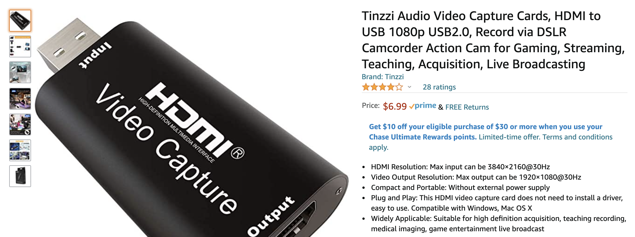
You can grab a better capture card, but it’s basically a waste, while they say they will take in 4K, they really wont and for the most part we are going to be downscaling them to 1080 or less anyway, and probably receiving it in at 640×480 or 800×600 to keep the framerate up (and we dont need higher resolution anyway!). However some might offer better colours, I havent seen it, but thats something left up to the reader.
HDMI Splitter ( $29 or $47 )
The two models from easycoolav are the EZ-SP12H2 (cheaper) and the EZ-SP12HAS (the more expensive one). If you are buying the cheaper one and its from Amazon/other third party, you want to check if its the newer GD32 model (ask, they will know) that provides slightly better colouring on the images and has a faster MCU. The more expensive one is not going to give you anything better for now but it has a bigger processor and hopefully with the new firmware it will be able to do BT2020 -> SDR better in the future! If you want to spend extra this and the LED strip are good places.
LED Strip ( $15/25 and up )
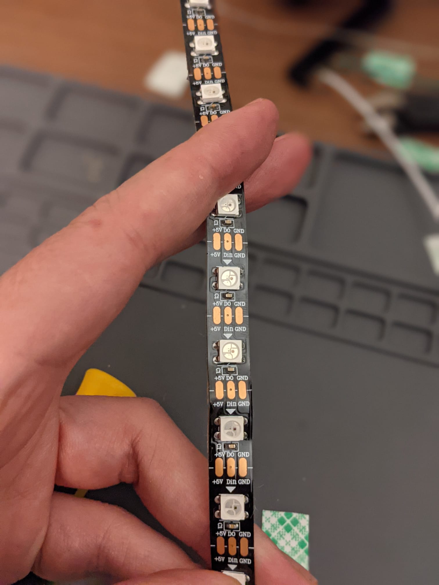
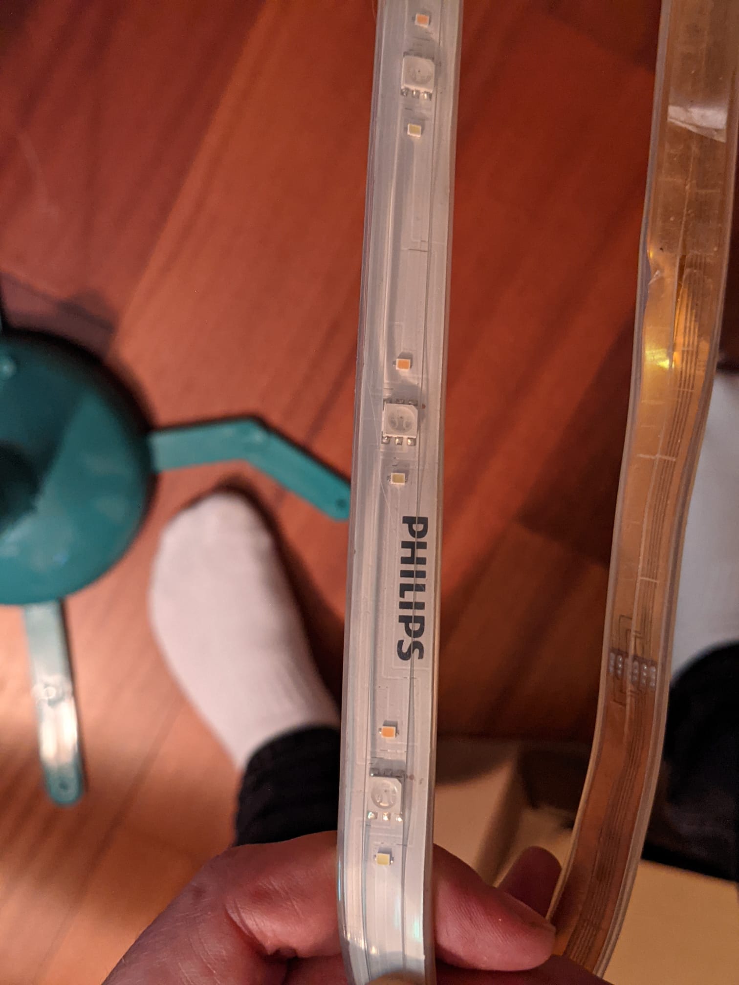
This really depends on the size of your TV and the density of the LEDs, from what I’ve seen they mostly come in 30 or 60 LEDs per meter, which determines how close together they are, for eg the philips hue strip has really spaced out and is the 30 LEDs/meter, I like them a little closer together so I have more colour “density” for my setup so I am using the 60 LEDs/meter. Above 60 LEDs per meter it starts getting really pricy, I’d love to try some but I’m not sure the value you get for the price will be worth it. The second thing with the LEDs is the quality, cheaper LEDs generally don’t match as well from what I’ve seen, but honestly this is light bouncing off the back wall of a TV, I’m okay with it for my setup. The last thing to look at however is the “white” for the LED strips, a lot of the whites are ‘cold’ and come out a lot more blue and some ‘warmer’ which come out a lot more yellow, you want to get the one that works best for your environment. The LEDs need to be WS2812 compatible unless you are prepared to dig through some code to make changes to the library!
Here is an example of the one I am using vs the old Philips Hue strip so you can see the spacing difference
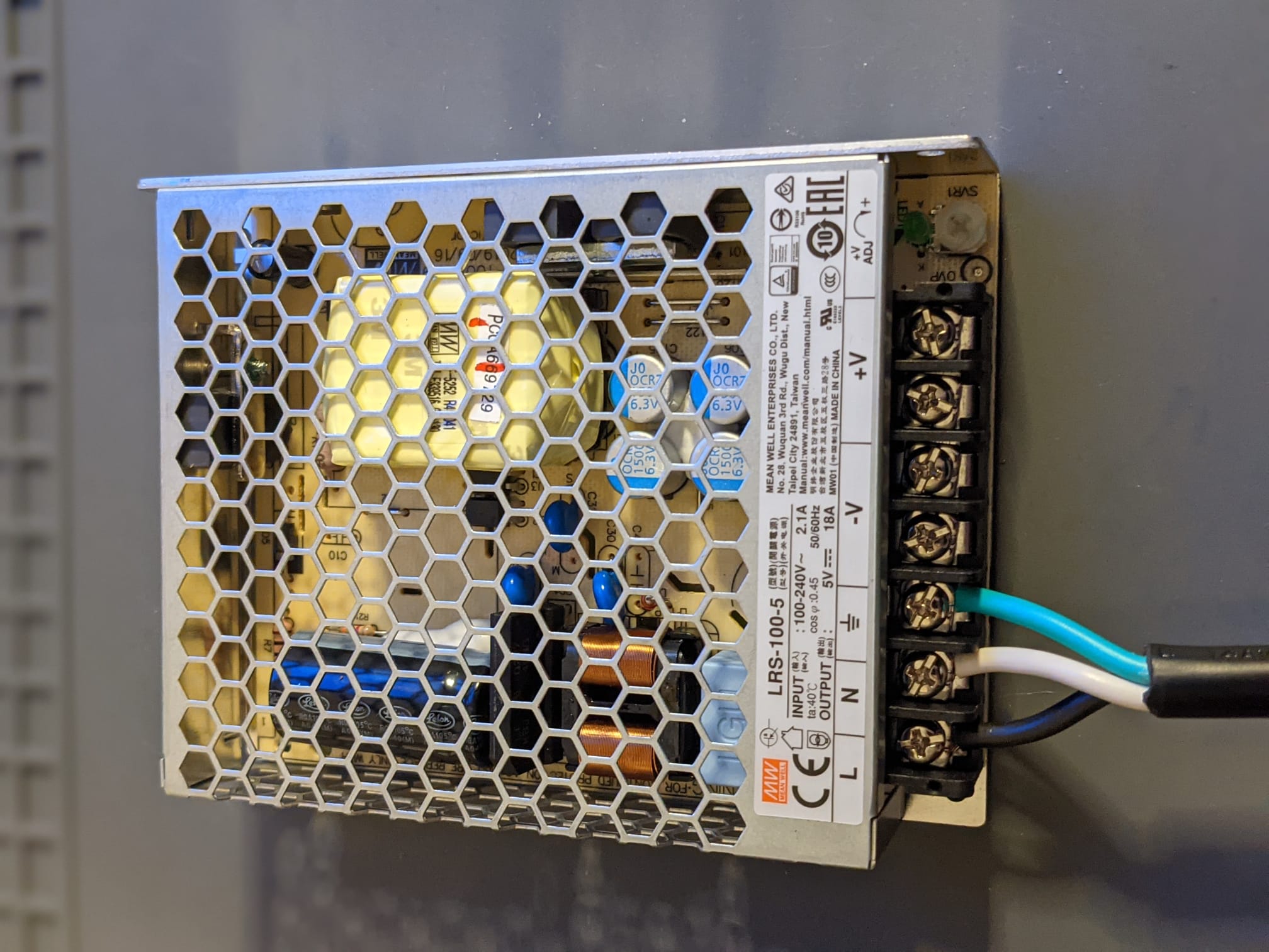
Power supply ( $20 )
The power supply depends on the LEDs , you need to provide enough power for the entire strip, and likely you are going to need to power the strip from either end. The back-of-a-napkin formula you should use is number of LEDs x 60ma (technically this is usually 50, but I like to be on the safe side since I am buying very cheap components) to determine the maximum current draw your setup will need. For my 65″ TV I have 270 LEDs so I need at least 16.2 A ( 270 x 60 = 16200mA = 16.2A). I really like the meanwell power supplies and they have some great ones available in the usual places, the only recommendation I have is to make sure you have the ones that are in the “open” cages as the sealed ones have fans that sound a bit like they are taking off and really ruin the experience of watching TV :)
MISC Items ( $20-ish )
The misc items are the additional things you need, some of these you can get away with, some you probably have lying around the house.
HDMI Cables – go look in the box of cables you should have thrown away, there are some in there. For the connection between the splitter and the Pi you dont need the highest quality cable, but between the splitter and the TV definitely use the good ones (HDMI 2.2+).
Pi4 Power supply
You definitely need a power supply for your pi, don’t try and use the Power supply above because the LEDs draw a lot and the Pi will really not be happy with that. These usually cost < $10 and you probably have something you can use at home, its just a USB-C power supply that can give up to 3A or grab one with the pi in the kit from canakit
SD Card – You can pick these up anywhere, I have a 32gb one just because its what they had at walgreens but I’d recommend at least 16gb, you don’t want to be pushing up against a full card and having to tweak things down and its only a few bucks different.
JST Connectors
I have some JST connector packs because they are really useful to do edges for the strips, I can just cut the strips to the right length and then solder the JST’s onto them which means I can connect two strips by clicking the JSTs into each other. I have a $10, 50 set from here , you are only going to need a set of 4 (and maybe just 3 if you dont want the bottom row), so you can prob just go to your local hackerspace and grab some, if you are in SF, grab some from me ( andrew blgh andrewmohawk dot com).
LED Mounting clips
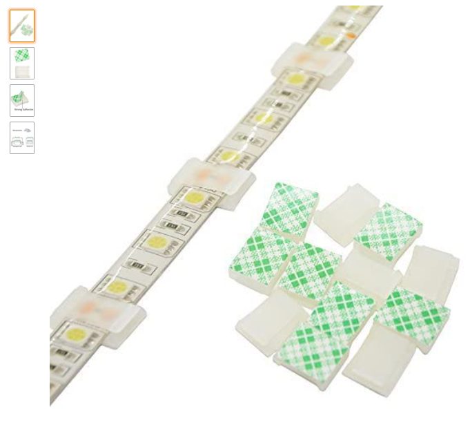
The LED strip you buy is likely to come with the 3M/whatever sticky side that you can put right on the TV, but if you don’t want to use that because it sucks (and it sucks for a lot of them) or you might want to remove it later, you can grab some strip light mounting clips that you can slide the LED strip into, I have a pack of 100 clips for $10 from amazon but it really is up to you how you want to mount them. They look basically like this
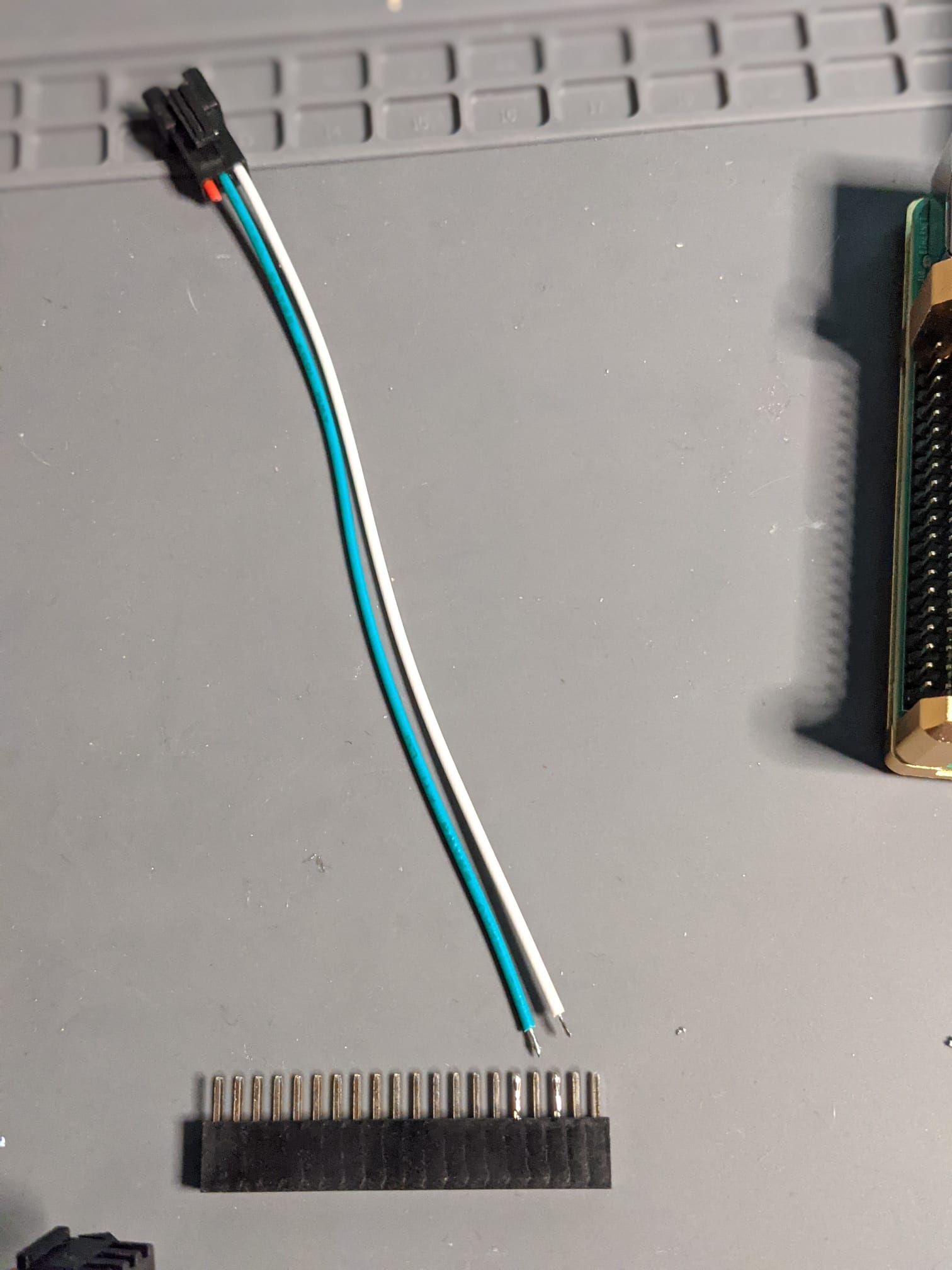
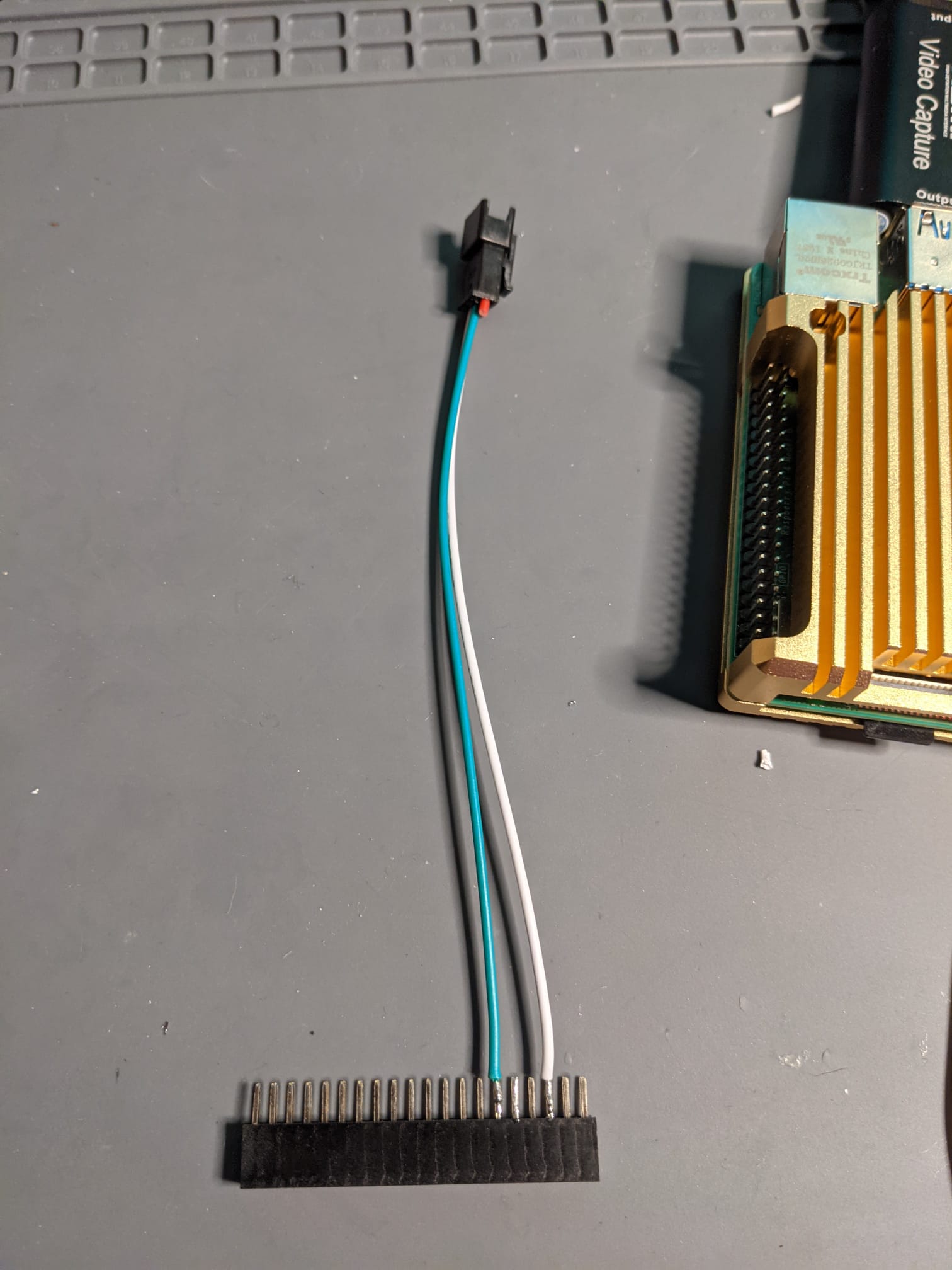
40 pin header
Either you can solder onto the header or you can solder directly onto the pins of the Pi, I prefer working with the header and I like having all 40 pins, even though I am only going to use 2 pins since I can always see how it is seated.
Building: Hardware
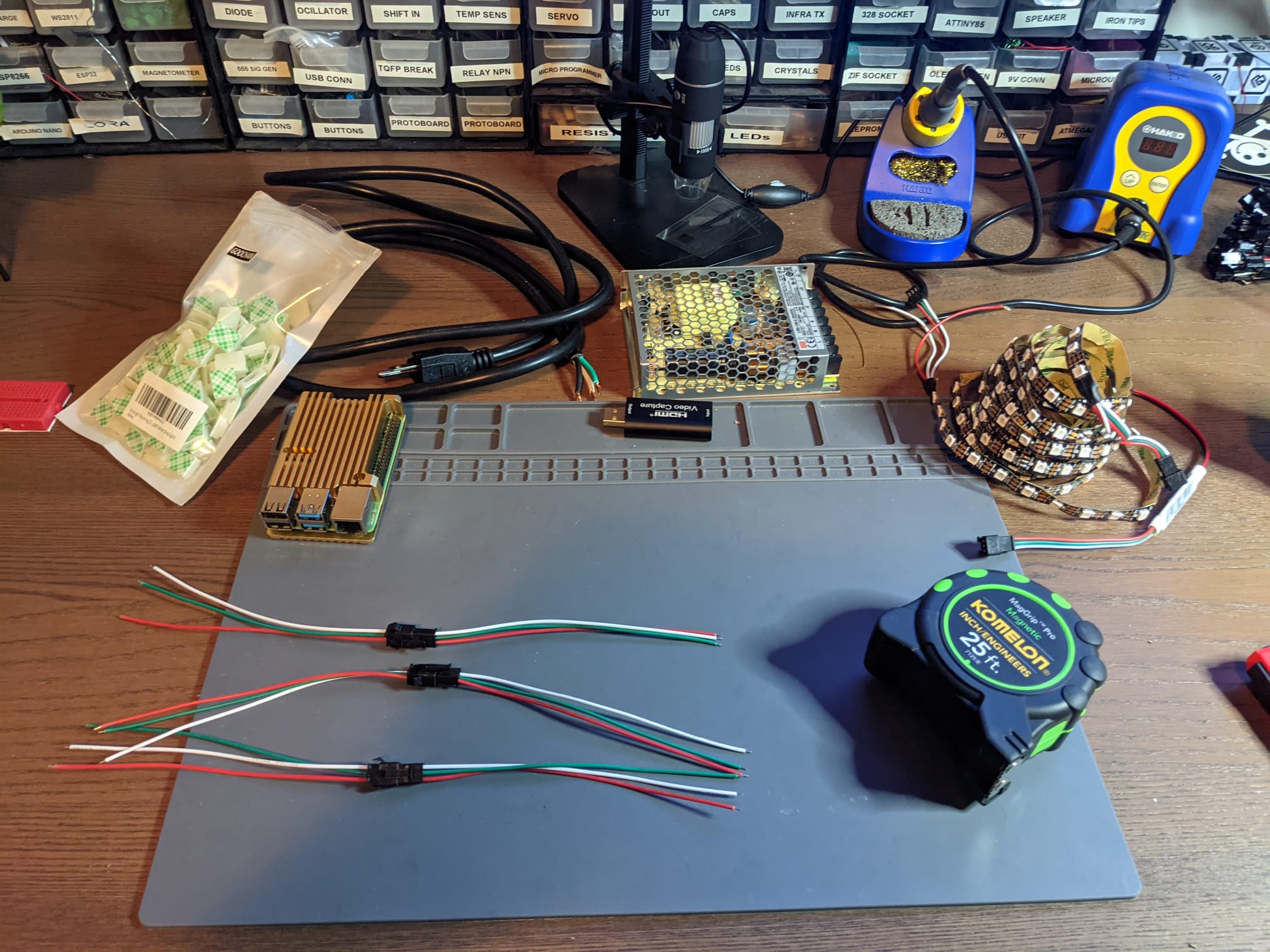
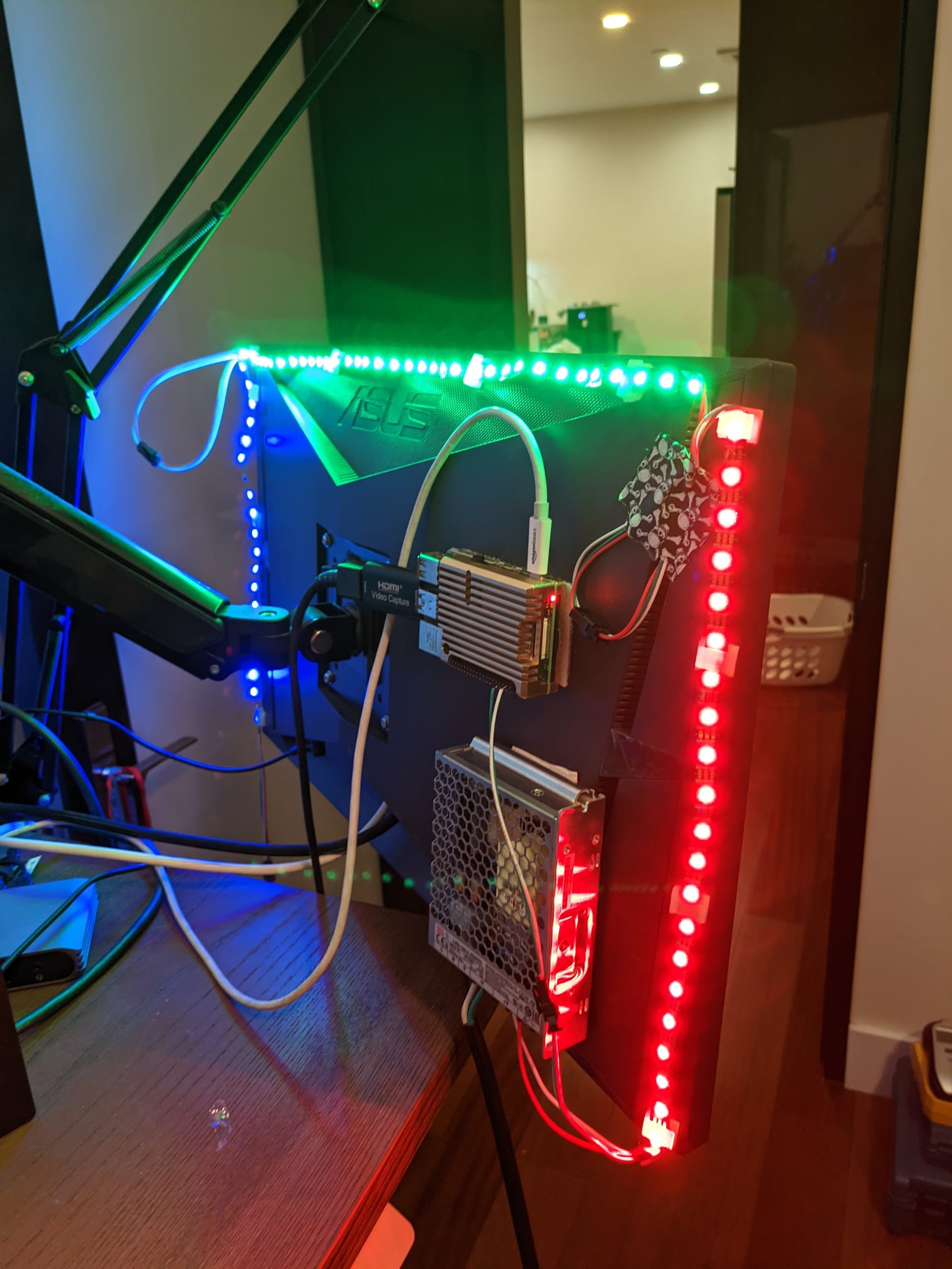
Since I already have it setup on my television I am going to show how to do this using a monitor I have on my work desk and and my Switch :) Get all the hardware together and lets get cracking!
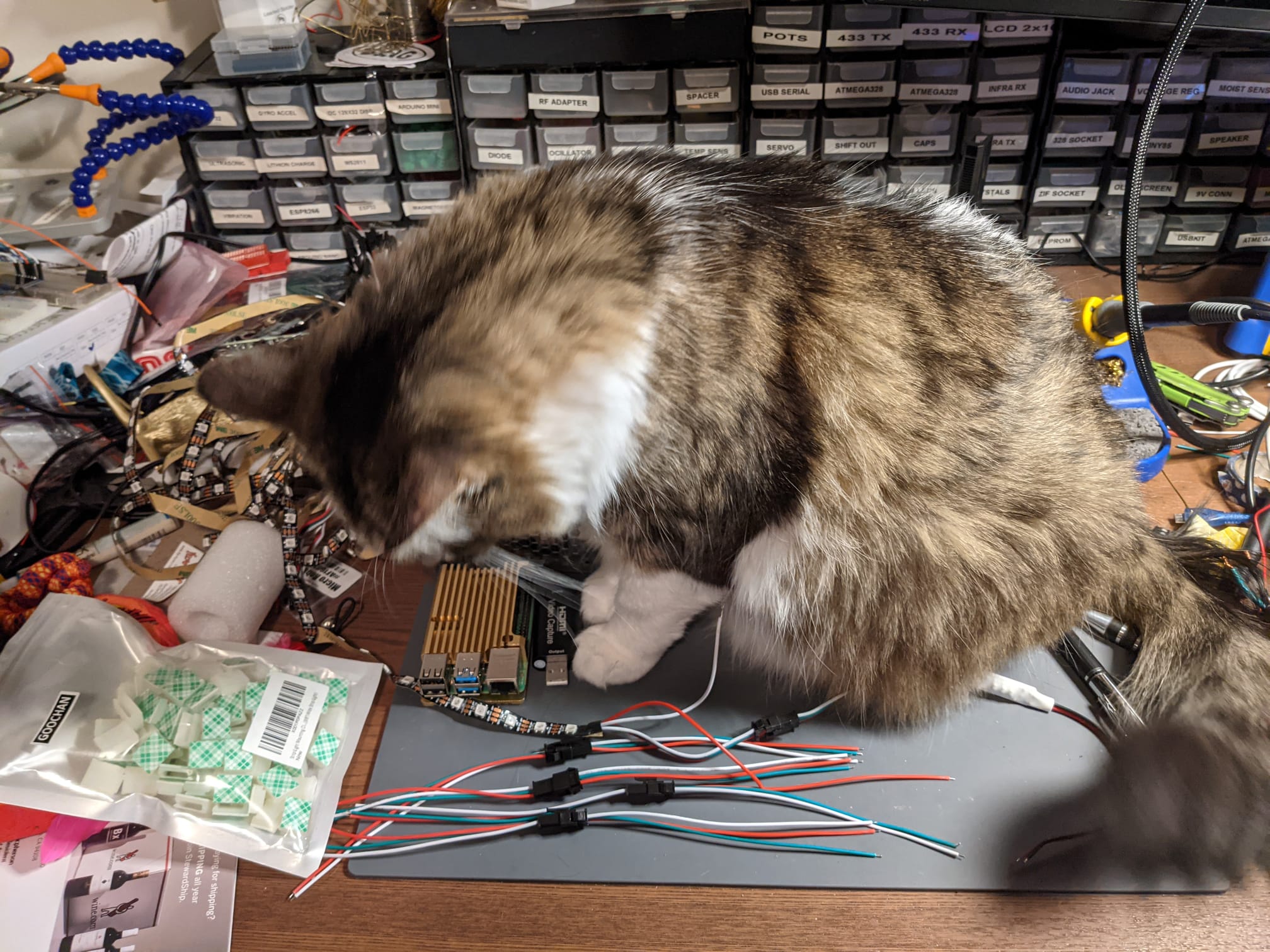
Having someone to help you with this is great, however I don’t recommend having a cat assistant.
Starting off you are going to want to get your LED strip and measure your television or display you are using.
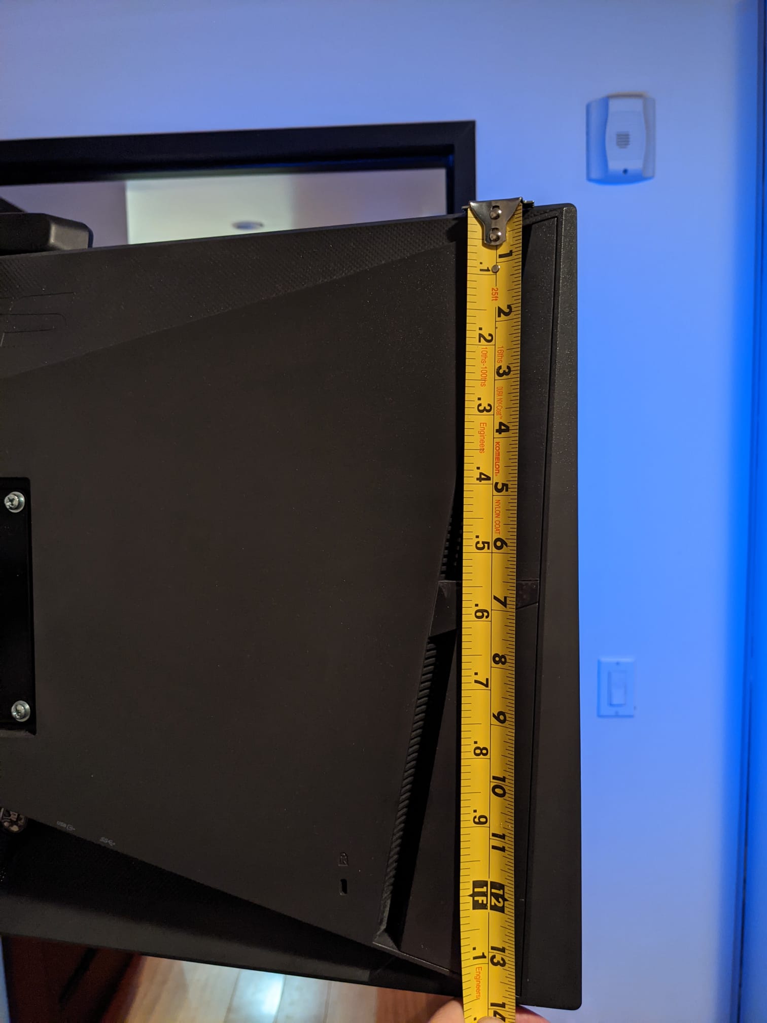
Ideally you want to actually hold the strip up to the display to figure out how many LEDs you need since you want them as close to the corners as possible.
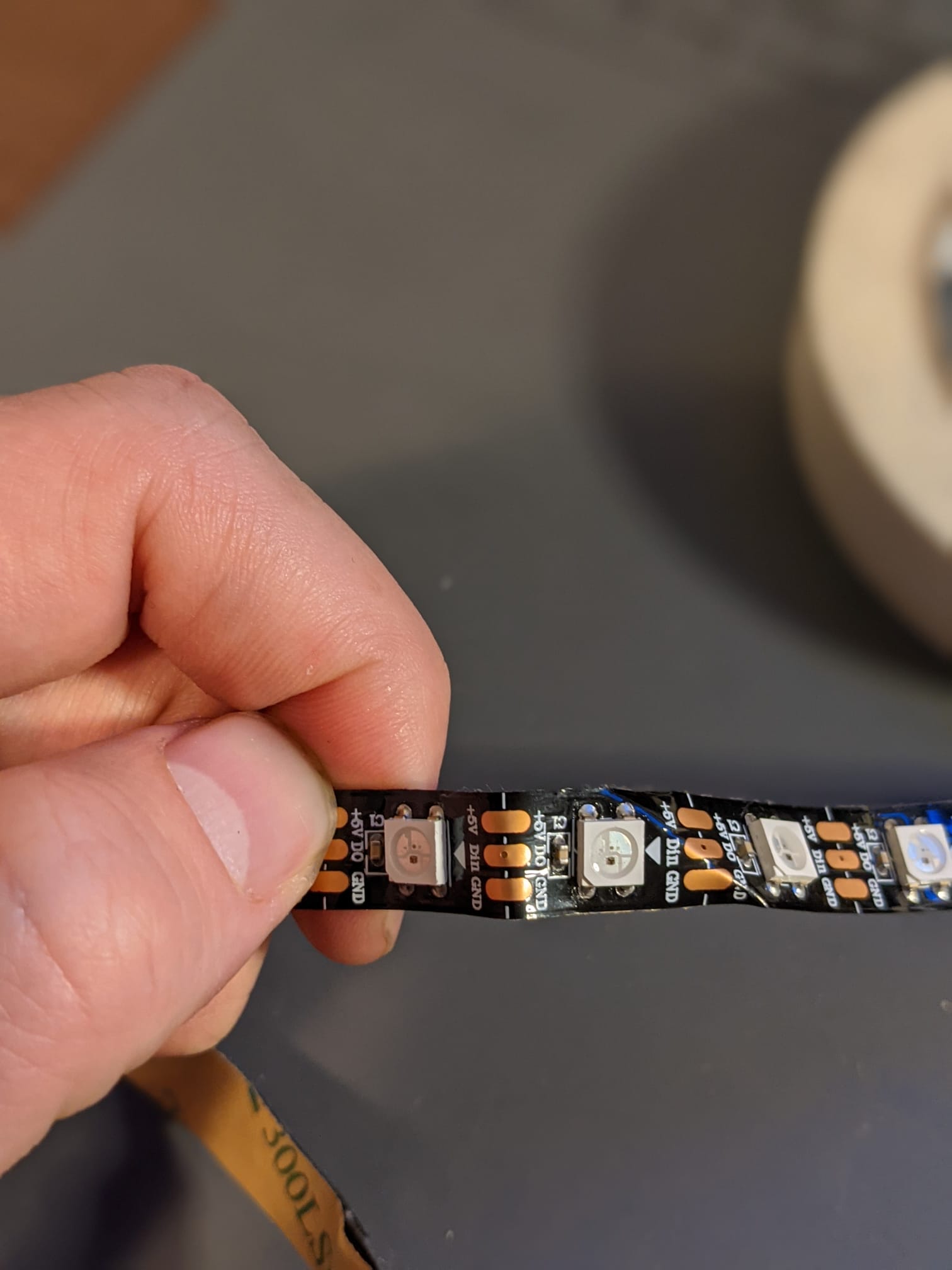
Next up you want to cut the LED strips to the right sizes, start at the side that already has the JST connector (the wirey clippy thing) and cut along the “joins” which are between the pads:
Now you should have 4 (or 3 if you dont want one at the bottom) strips, one that already has the JST connector as above and the others that do not!
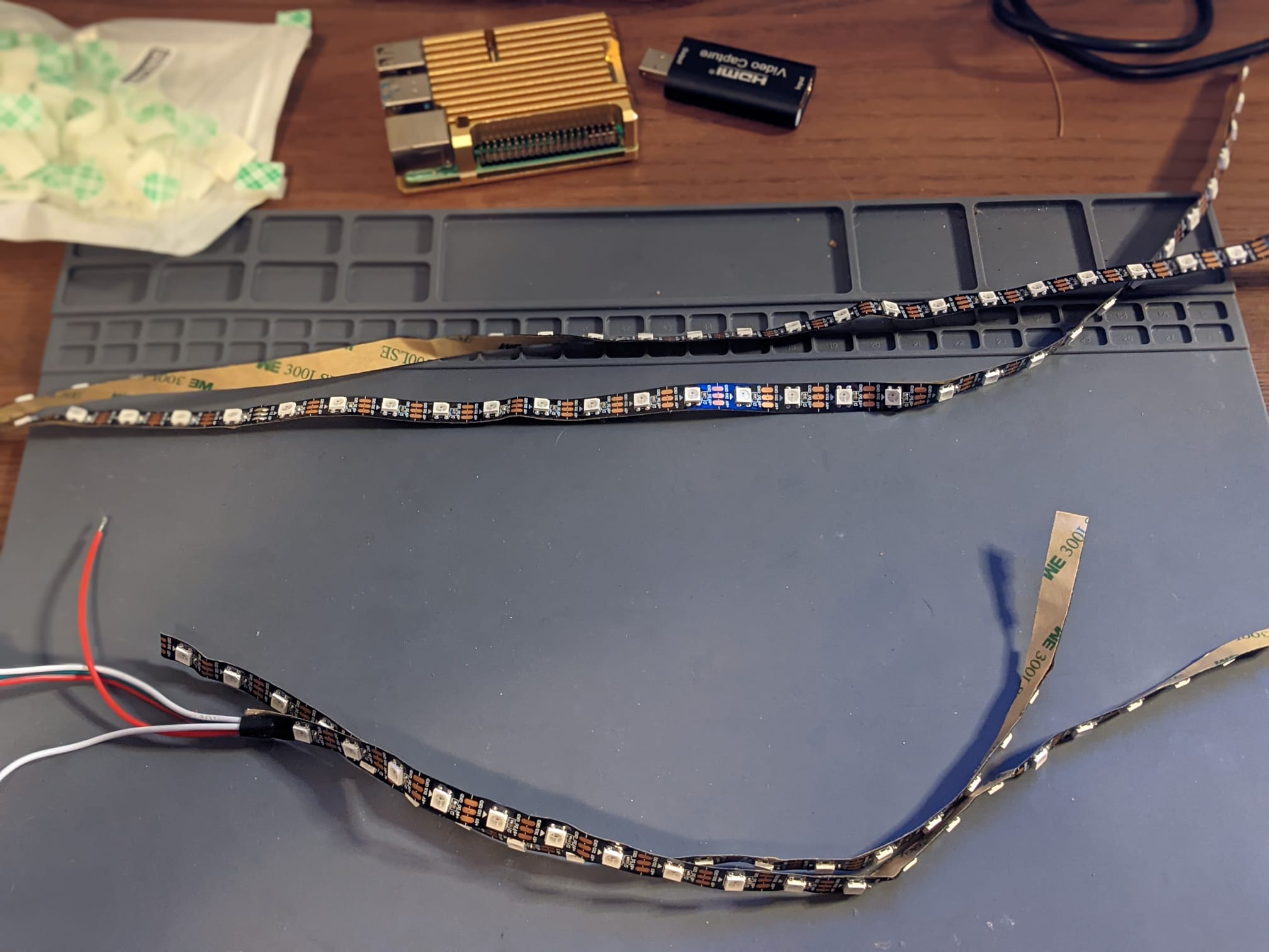
Now we need to connect these together so we can attach them to the display, do this off the screen since it involes soldering. Lay the strips down in the right order going the same direction you cut them in, there are usually arrows to show you as well, the strip is not reversible if you have it the wrong way round it will break :( I like to use the JST’s because the clip nicely together, I haven’t trimmed mine to be reasonable sizes, but I recommend you do so you don’t need to tape the random loops down (see later photos).
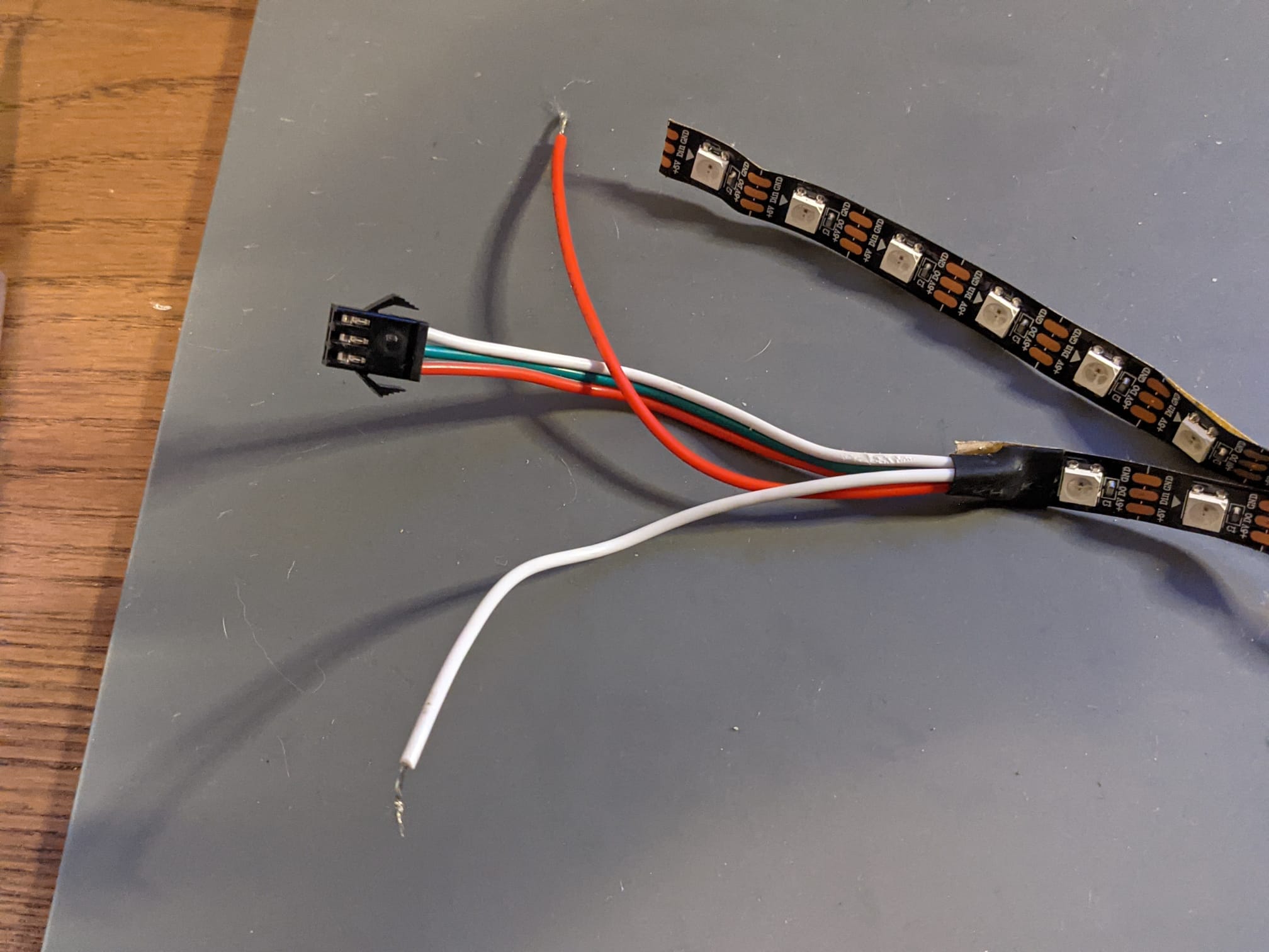
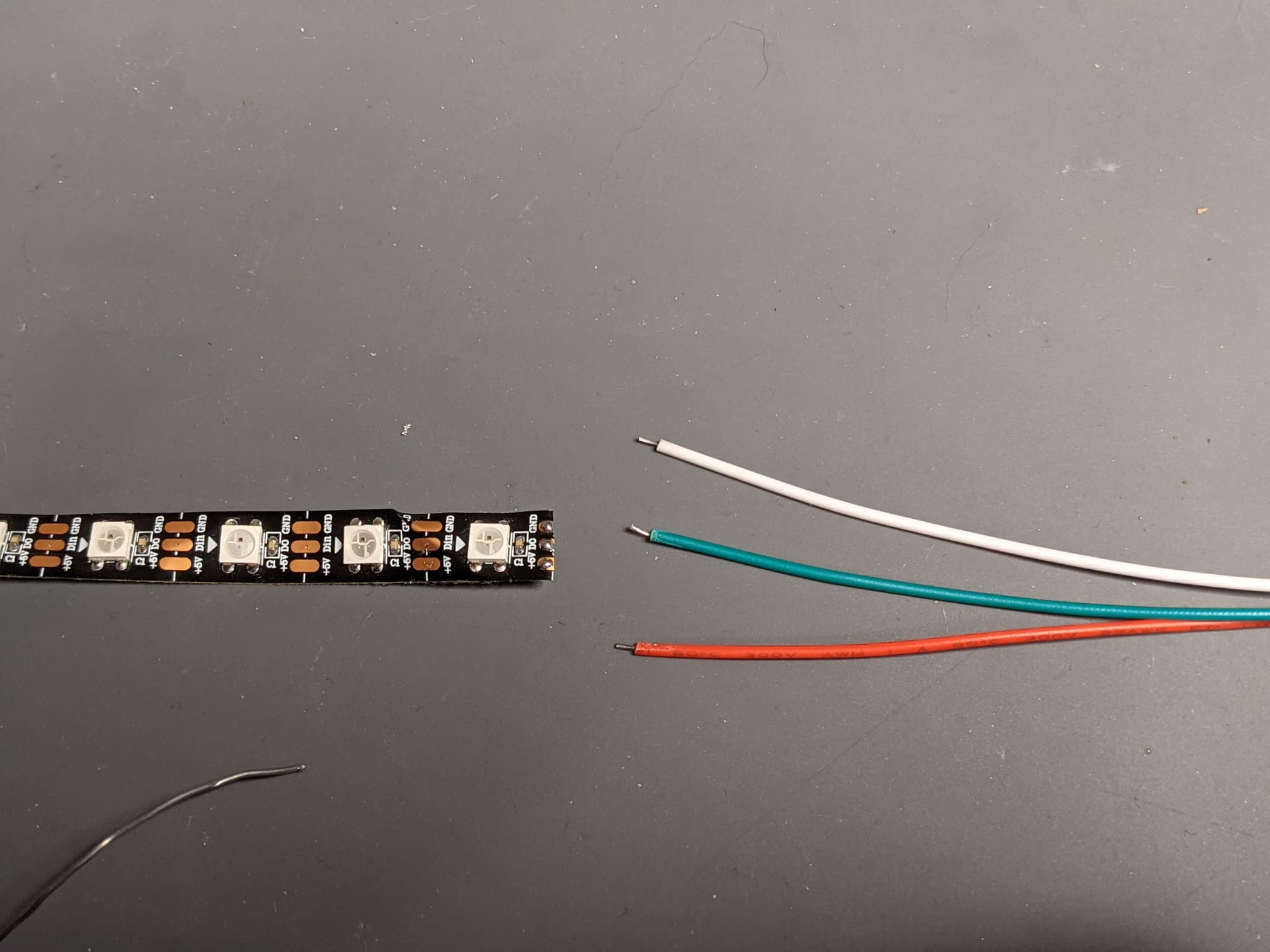
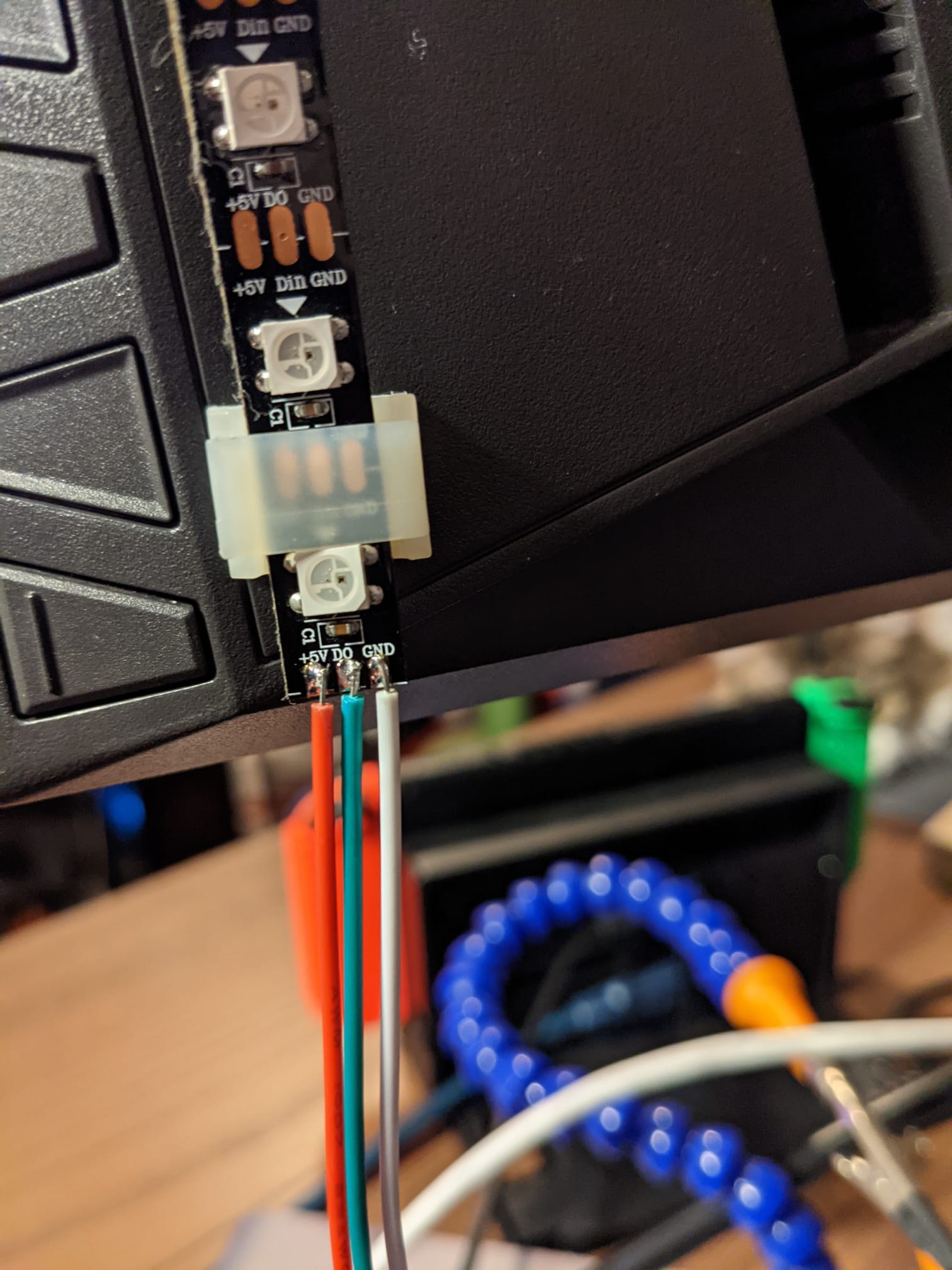
To connect the JST’s it just takes some really simple soldering, add some solder to each of the pads on the strip and the solder the wires from the JST connector on. RED for +5v, Green for Data and White for GND. Remember to make sure you have the right F-to-M or M-to-F for each JST so you dont end up having to redo it. Each edge connector on the strip should look like this when soldered:
Now simply move along the strips wiring each connector in the right order (remember its not reversible) and join them up with the JST connectors.
Please note you need to connect the strip as though you were looking at the screen from left -> top -> right -> bottom so it wraps clockwise starting at the bottom left
Now lets get the power supply going, connect the power lead you got with 3 prongs to the correct terminals on the power supply:
If your LED strip came with a tester (its a small device with 5v + GND on one side and a JST connect or on the other), now is the time to do a quick test of your strip before we attach it to the display. To do this connect the 5V and GND of your tester to the 5v and GND terminals on your power supply and plug it in. Here is a quick video of me testing mine:
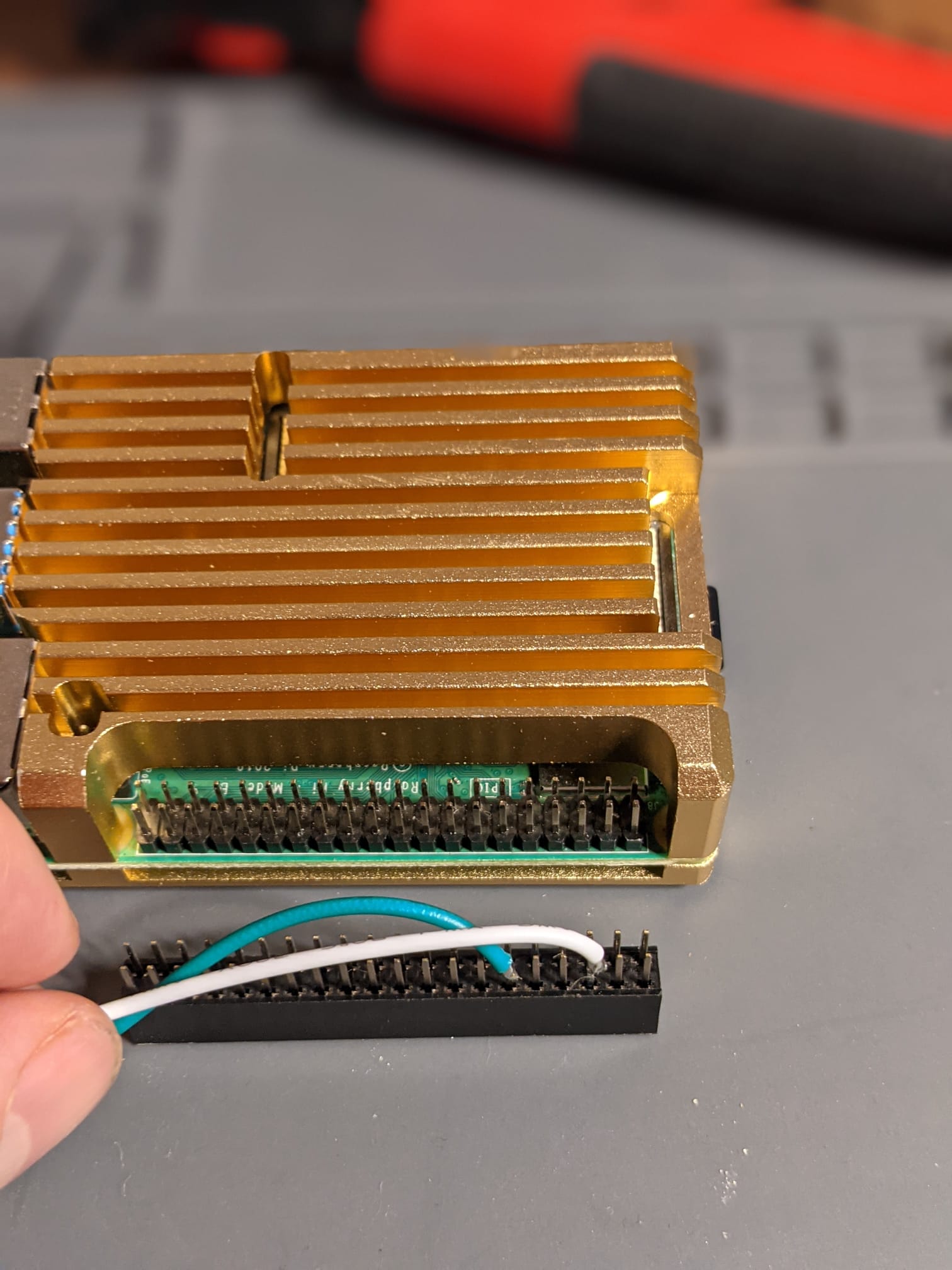
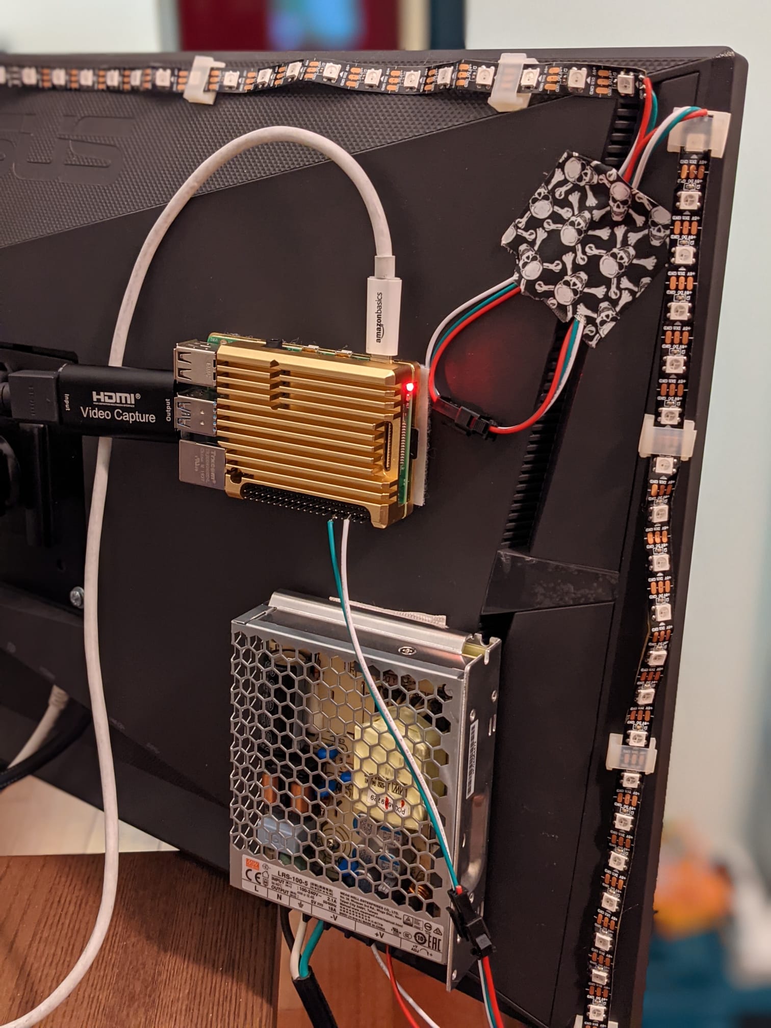
One you are happy with the power supply and the LED strip lets move on to the Pi hardware side. Since the Pi is sending out the data to tell the LEDs to turn on/off/colours/etc it also needs to work from a common ground, so you want the ground shared which is why we need two connectors. We are going to connect to the third and sixth pins on the outside row starting closest to the side of the board away from the USB and ethernet.
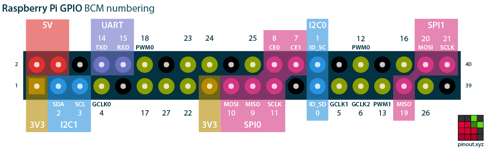
In this picture that is from the top left the third (GND) and 6th (Pin 18 PWM0).
I like to remove the power connector on my JST wire, just keeps it a bit cleaner and means its less likely I’ll make a mistake. I also like to use a 40 pin header so I can detach it if necessary, but you can also just solder directly to the Pi as well. Here you can see how I have soldered it on and how I will connect it to the Pi.
At this stage we have all the hardware setup, you can now connect the strip to the power supply. Depending on the LED strip and the amount of power needed you might want to connect 5v and GND not just to one side but to both sides of your LED strip. Generally you need to do this if you see that some of the LEDs at the end are not the correct colours (ie the whites are dimmer or a slightly different colour).
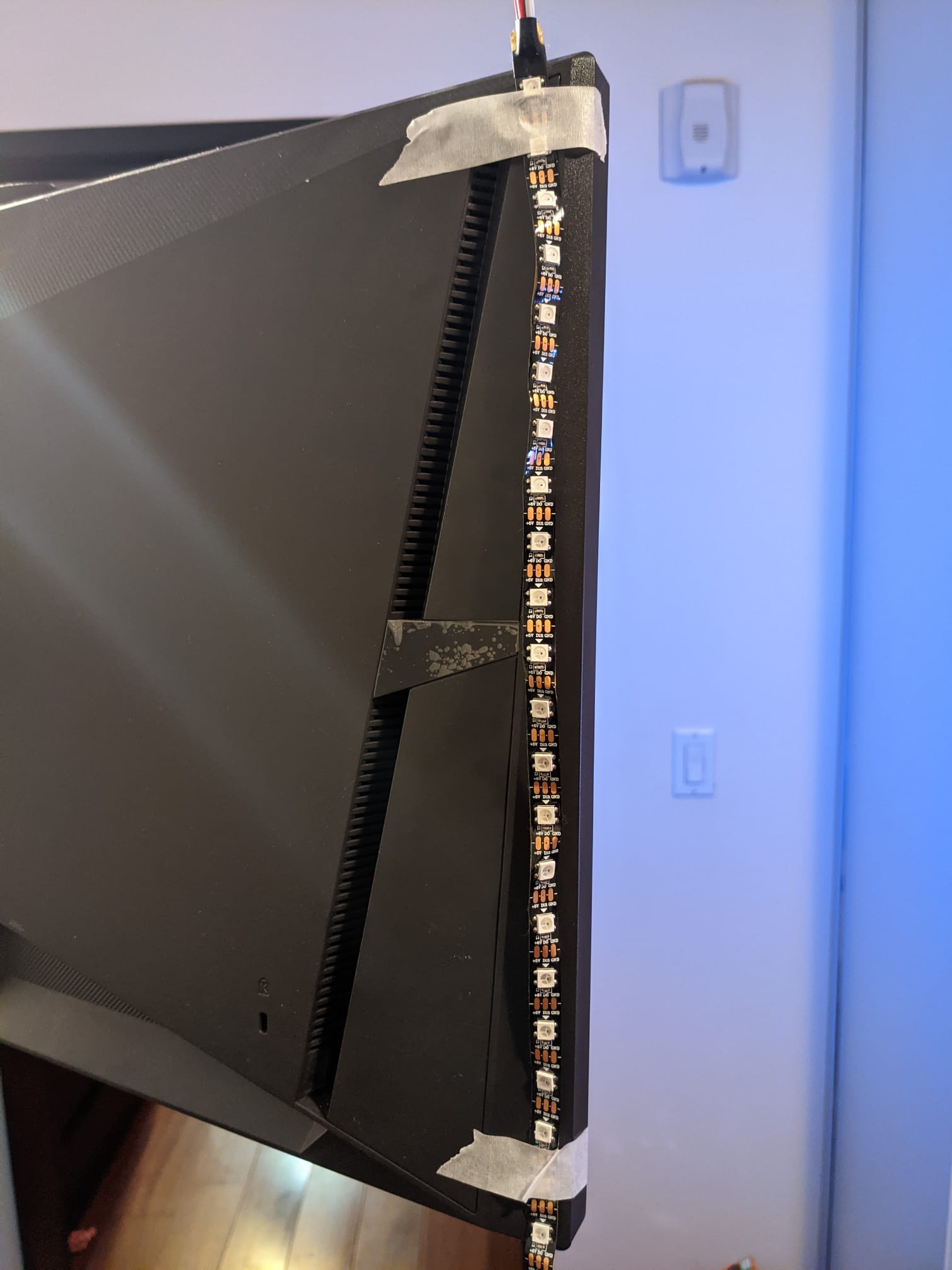
Next you can connect the strip to the back of the screen in with the holders or use the 3M tape on the back of it or however you else you want to hold it in place.
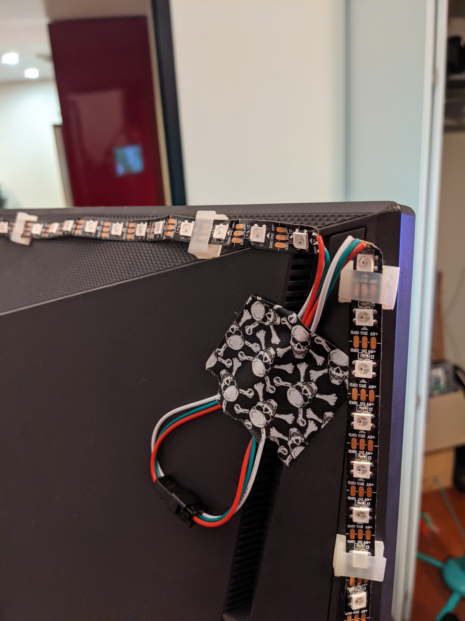
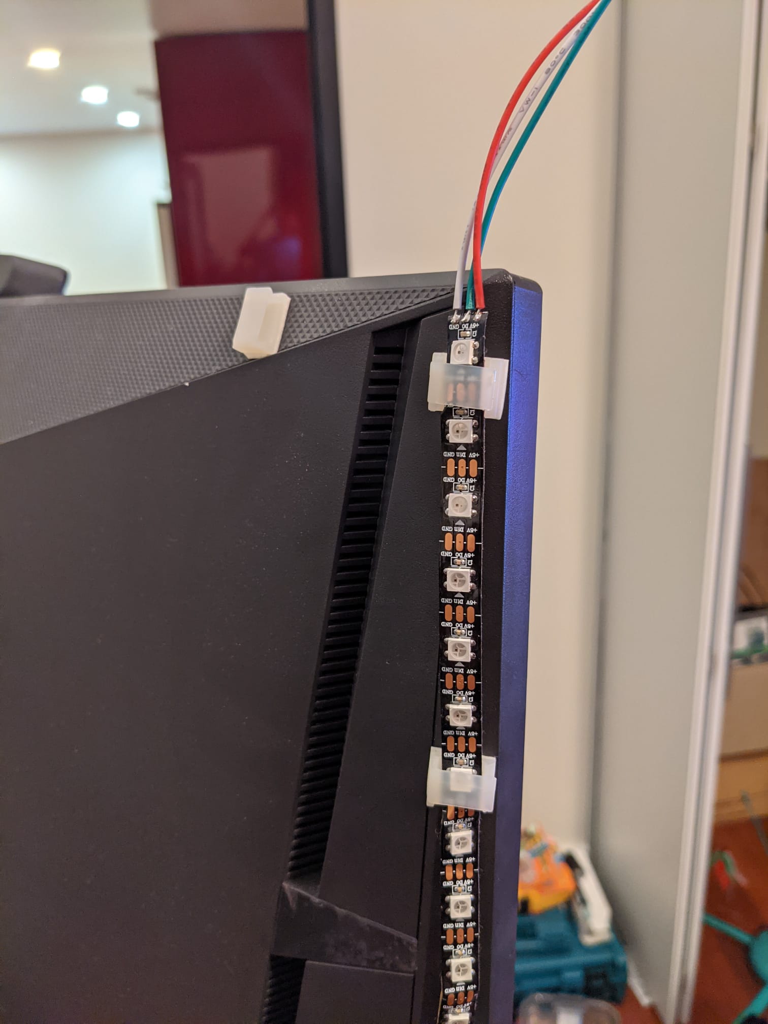
(Here you can see why I suggested cutting the JST connectors so you dont need the skull tape to tape it down like I did!)
Lastly, depending on how you set it up you might want to attach everything to the back of the display. I use some velcro tape to get mine on and it comes out pretty nice to be hidden behind the display:
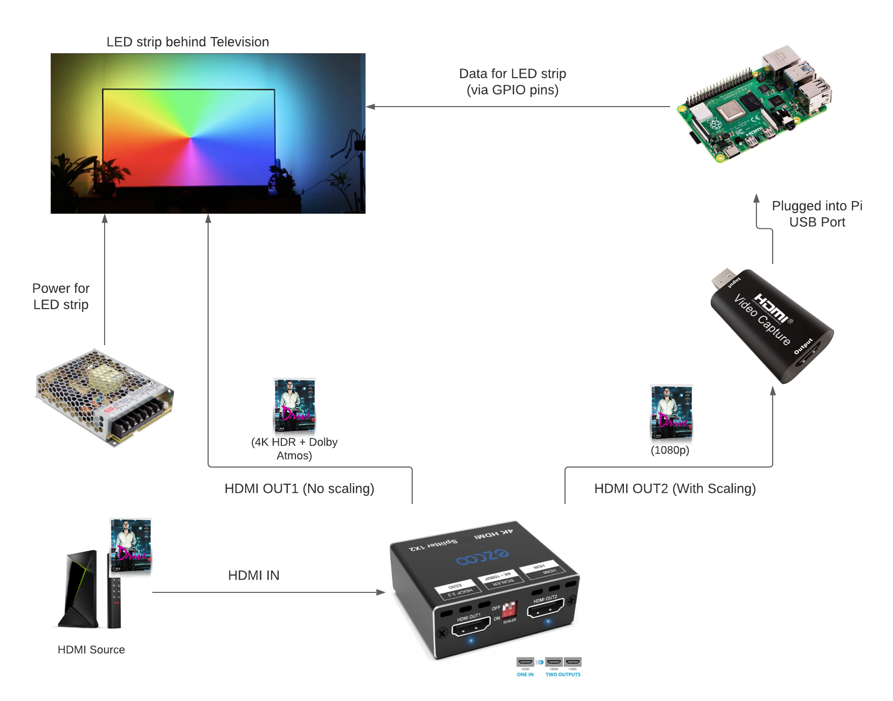
The flow for how this should be connected is as follows:
Building: Software
This should be a much shorter section and the raspberry pi software universe has come along so much since I last touched it, it was a pleasure to use!
Grab your SD Card, get it in your machine and download the Raspberry Pi imager
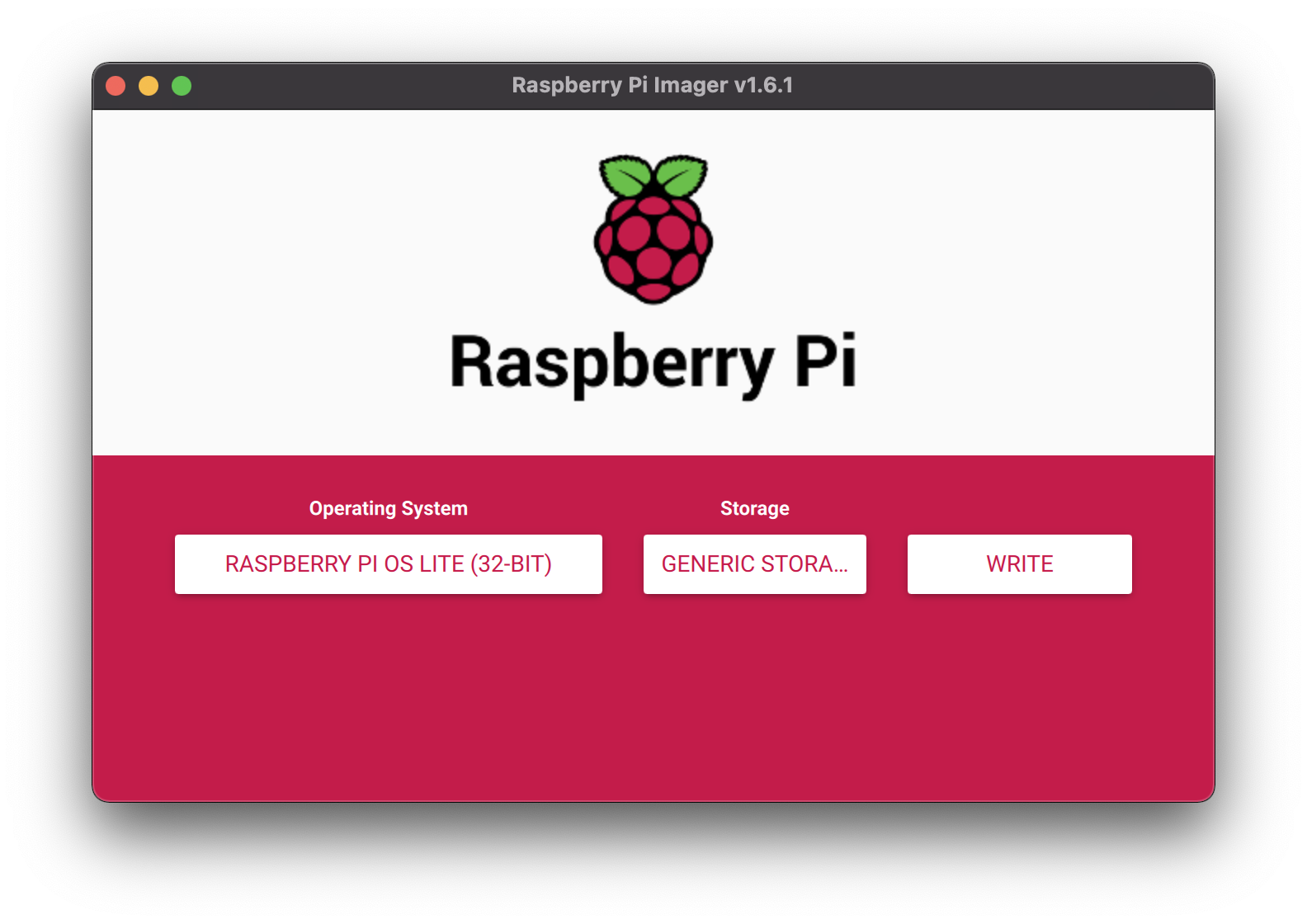
Select the OS Lite, the SD card and hit write. Once thats completed your SD card will be prepared to run Raspberry OS. We need to setup SSH so that we can connect to it and WPA_supplicant so that it automatically connects to our wireless network.
For SSH just create an empty file called ssh and place it in the root of the SD card. Next create a file called wpa_supplicant.conf (great catch that this needs the .conf by @robster2443) that looks like this:
ctrl_interface=DIR=/var/run/wpa_supplicant GROUP=netdev
update_config=1
country=US

network={
 ssid="MYWIRELESSNETWORK"
 psk="PASSWORD"
}
Just replace the MYWIRELESSNETWORK and PASSWORD with your details and copy it to your root of your SD card (It should appear as ‘boot’) in your file manager.
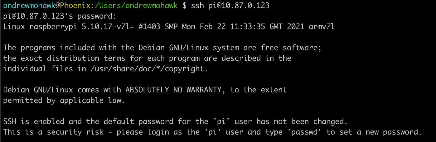
Next you can put the SD card into the Pi and power it on. It will automatically connect to your wireless network and you should be able to find it. You can either use your router interface to identify it or scan with nmap, there are many guides available for this.
Now you want to SSH into your raspberry pi, I’m on a mac so I will be using a native terminal, if you are on windows you can use putty or whatever ssh client you prefer. The default username is pi and the password is raspberry. You will be asked to change the password, this is a good idea, do that.
Now its time to do the install, if you want a one liner its simply:
wget https://raw.githubusercontent.com/AndrewMohawk/Aurora/master/install.sh -O - | sudo /bin/bash
Once you type that you should see the install automatically happening for you
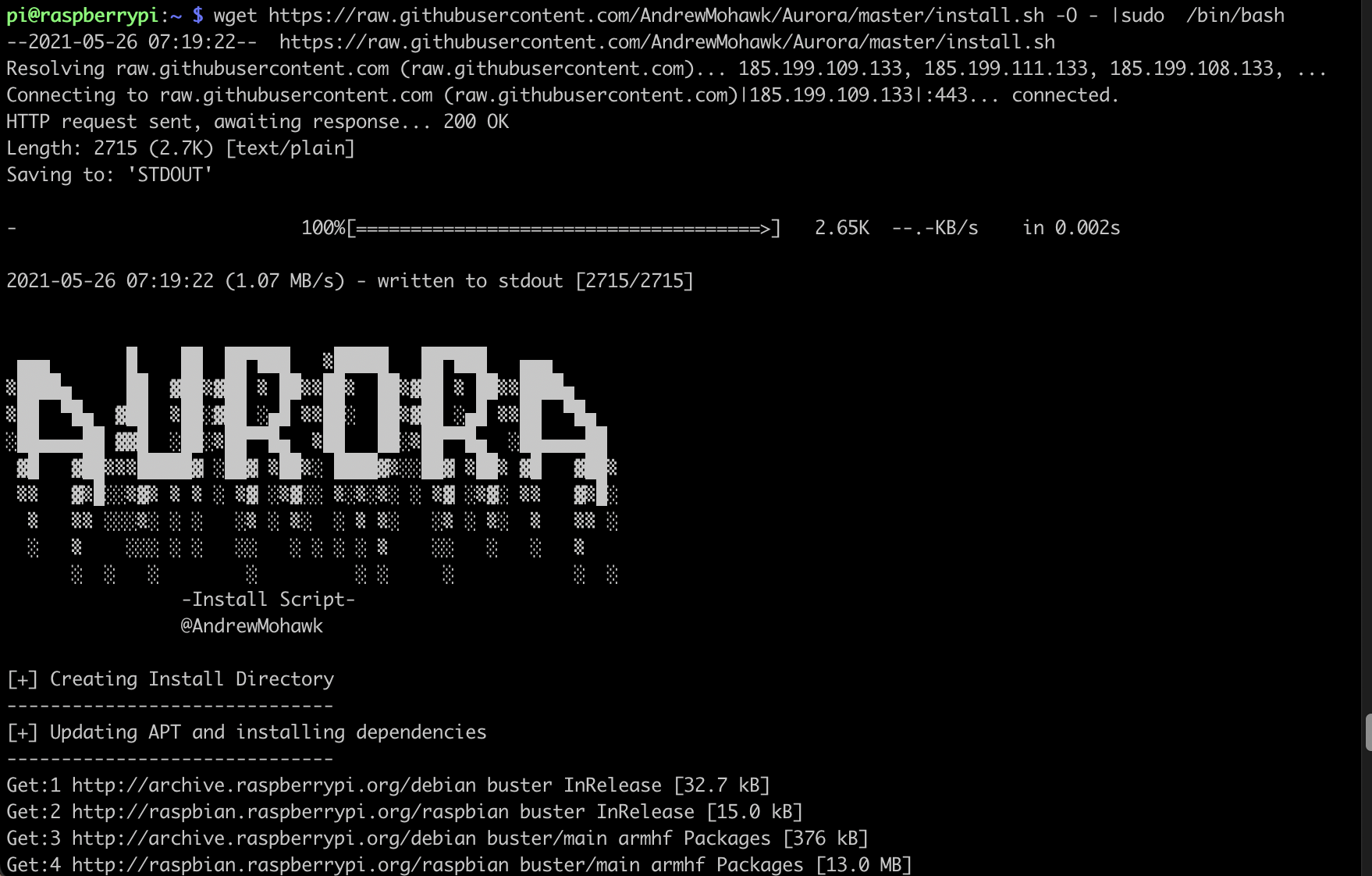
—– This will take a lil bit as it installs all the pre-requisites for this —-
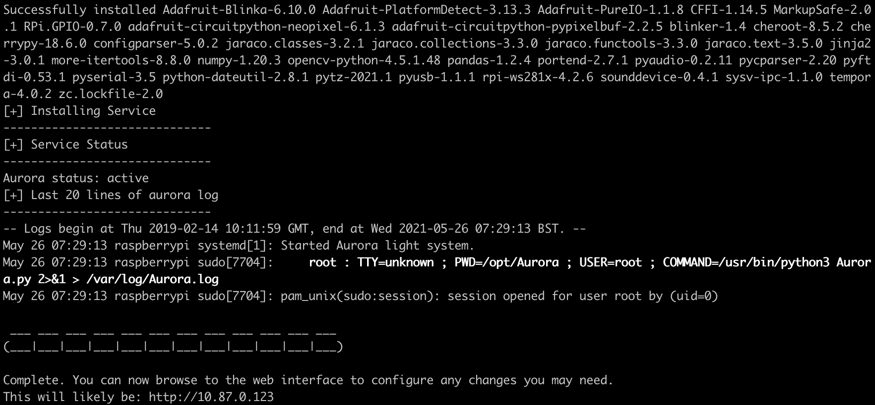
And we are done! Everything should be set up and now its just the final step of configuring it. It will also tell you the web interface you can likely connect to for this.
Building: Config
So now it’s running, but it doesn’t know exactly what you your setup is, so we need to configure it. The final line of the install will tell you that you can browse to http://<ip_of_your_pi>/. I recommend doing that on your phone. Once it loads up click the configure screen:
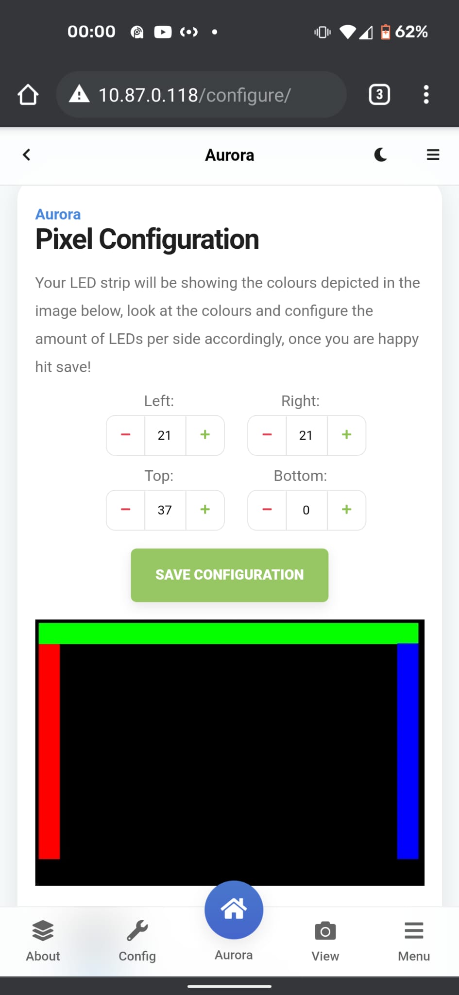
Here you will see the lights behind your display light up to match the config on the screen.Either configure it looking at the display you set it up for, or take a peak round the side (this is better) and use the + and – buttons to set how many LEDs there are, these will automatically adjust and you can get to the right number, once you are happy just hit save.
Building: Usage
The usage of the interface should be pretty straight forward, just browse to the main screen, select the plugin you want and click ‘load extension’.
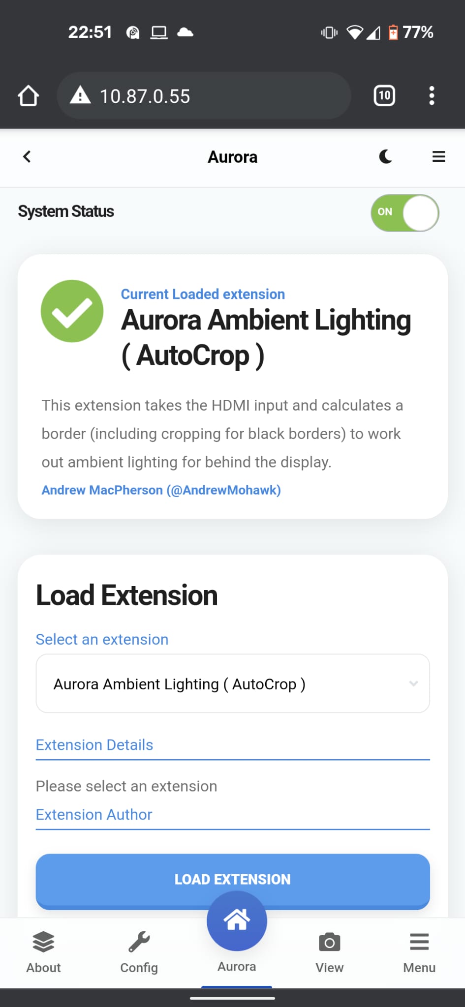
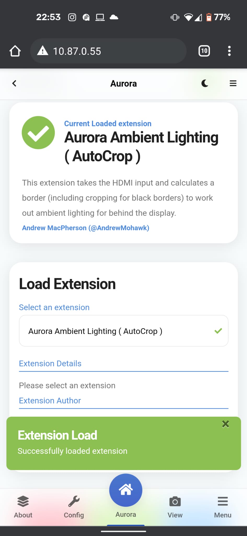
Likely if you want to just do this once and select the “Aurora Ambient Lighting ( AutoCrop )” to have a fire-and-forget setup. When your display comes on the lights will and when your display turns off the lights will as well :)
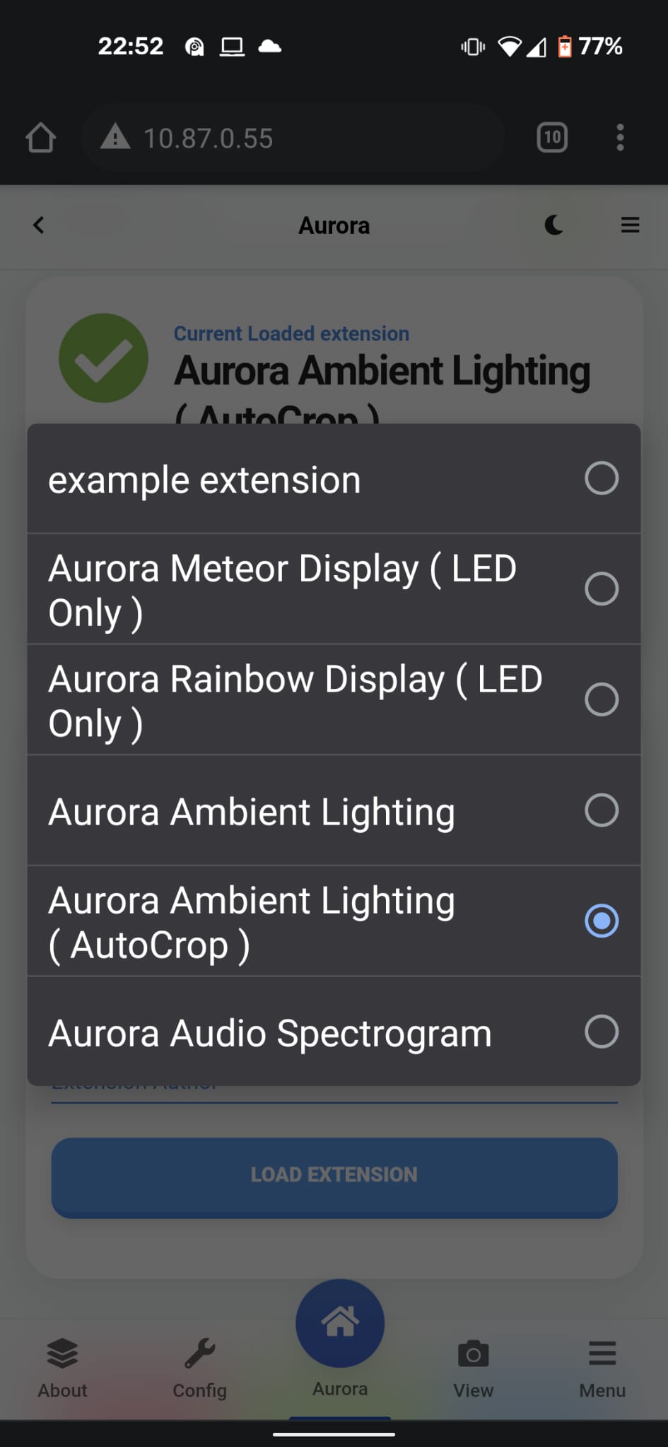
The extensions that come with it by default are as follows:
- Aurora Ambient Lighting – This takes the whole screen resolution as is transposes the border to the LED strip, its faster than the the autocrop version but it doesnt.. well.. autocrop. You shouldn’t notice the speed, but technically this one is faster.
- Aurora Ambient Lighting ( AutoCrop ) – It will ‘autocrop’ based on the darkness around the edge of the image, its the most useful for a setup and go feel, it should autocrop when needed and just work ™
- Aurora Rainbow Display ( LED Only ) – This will do the ‘rainbow’ display everyone seems to love, its a slowly moving colour wheel that looks great! Does not care whats on the screen
- Aurora Meteor display ( LED Only ) – This will create a meteor effect where it will randomly select a colour, ‘meteor’ around the screen and then when its back at the starting point pick a new colour and repeat
- Aurora Audio Spectrogram – This is actually similar to the rainbow display but will light up sections of the strip based on the amplitude of particular frequencies, great if you are just listening to like spotify or something.
- example extension – an example extension for people who wish to write their own for Aurora
I will likely do a more detailed writeup on the usage, but if there are any questions feel free to ask away!
Enjoy!
Cool found it! I will see what I can get here is saf efrika and try to build it! Thanks!
I’m curious why you soldered two red wires onto the LED strip when you cut off the red wire on the pi end anyway? Shouldn’t you only need 1 red wire going to the power supply?
Ah, I see thats a little confusing and my fault for not explaining it better. So the one side has both a JST connector *and* power+gnd, so I didnt actually solder anything there, I just removed one power line from the JST+wire connector I am joining to the Pi so I dont make a mistake!
That came out so damn cool. Thank you for sharing. I can’t wait to start collecting supplies and try this out myself
If using an AVR with a 2nd output, could I just use that instead of the splitter?
How hard would it be to have Home Assistant tell it to switch between modes?
For the first – Absolutely, really you just need HDMi with whats going to the display sent to the Pi
As for the second, its a simple webapp with some Ajax calls, you could easily just create the POST request yourself to get it to switch :)
hello, i use this capture device
https://ae01.alicdn.com/kf/H3188aa636de84984a35392cd2faa237bx.jpg
https://www.aliexpress.com/item/1005001266503369.html
4k 60 fps, no hdmi splitter need, work fine whith hyperion, proved on nintendo switch and nvidia shield
Heya, This will also do 4K 60fps with HDR. The one you linked to is really just the splitter and capture in one device, however it doesn’t look like its doing EDID passthrough, so that means that its limited to the EDID modes it currently knows and uses as well as what it can downscale from. Ideally you want to be able to pass the EDID from the device that has the media on directly to the display so that you can get the best quality in terms of Visual *and* Audio (ie, all the Dolby/THX/Whatever).
That being said this does simplify the setup a little if you are okay with those limitations
How limiting is the issue with HDR? The vast majority of the content I watch is now HDR so it would be good to hear/see more about the issues with it and the success of the work arounds.
Here is Avatar in HDR: https://www.youtube.com/watch?v=1ptNaA4q34k
Hi. Great project! Does Aurora do HDR tone mapping like you get with HyperHDR? When passing HDR content through the video capture card, it tends to look dim and washed out.
Unfortunately not, I only recently came across it after building this, but I believe Hyperion does this. The setup is a little different, but you can almost get there with the same parts!
Any ideas on a capture card that’ll work with 24Hz so blu-ray, Amazon and Netflix etc can run at their native refresh rate when outputting 1080p? All the ones I’ve tried so far only do 60Hz ?
Unfortunately this I do not know!
The cat photo and caption made me laugh aloud.
The perfect intermission of a tech-laden treatise.